This chapter is part of the TwinCAT 3 Tutorial.
When we talk about “Safety” in industrial automation, we’re talking about specific functions of our machines, equipment and our processes related to the safeguarding of people. In most places there are legal requirements for machine safeguarding, and those regulations are generally based on national and international standards (e.g. CSA Z432-04 in Canada), but can vary between regions and nations. It is generally the role of a Professional Engineer to at least review and stamp the design of a safety system, though this can vary between jurisdictions.
Safety systems concern themselves with the control of energy. All sources of energy and all stored energy in a system must be accounted for and controlled. This includes electrical, pneumatic, and hydraulic sources, and includes potential energy stored in suspended loads, springs, compressed air, and kinetic energy of moving parts. Safety systems work by interrupting sources of energy and controlling potential or kinetic energy. Safety systems also involve proper mechanical guarding of a machine so that operators can’t come in contact with dangerous areas of the machine while sources of energy are connected or potential energy is uncontrolled.
A properly designed safety system consists of process, mechanical, electrical, and (increasingly) software elements that combine to form a safe working condition for machine operators and maintenance personnel. The demands on the reliability of the electrical and software elements are strong enough that ordinary electrical components and PLCs are unacceptable for use. In general (and this depends on specific cases) electrical and software components must be designed in such a way that any single component failure won’t lead to a loss of safety function, and the failure is detected and reported, and prevents further operation of the machine until it’s repaired.
Take, for example, an electrical relay. A typical relay is unsuitable for use in a safety system for at least 2 reasons:
- The relay can fail (typically by contact welding) in the “on” position resulting in the loss of its capability to interrupt a source of electrical energy.
- We typically detect failure of a relay by monitoring a normally closed contact. Depending on the construction of the relay, the failure may not be detected if the normally closed contact isn’t mechanically linked to the normally open contacts.
In order to reliably interrupt an electrical energy source in a way that a single component failure doesn’t cause a loss of safety function, and the fault is detected, you typically use two force guided contacts relays. The use of two solves the first problem of single point of failure, and the use of force guided contacts solves the second problem of reliably monitoring the relay’s state.
You can conveniently purchase a combination of two force guided contacts relays in this configuration, but it requires an external monitoring system to check for proper function. You can also purchase a “safety relay” with the two force guided contacts relays and the monitoring function all built-in.
Safety PLCs such as the Beckhoff EL6900 are capable of providing the monitoring function. Importantly, input devices such as e-stop buttons, gate switches, light curtains, and safety mats are also constructed with redundant components and must be monitored for correct operation, and the EL6900 can provide monitoring of these components as well.
As you can imagine, there are special requirements placed on the design of a Safety PLC. Just like any other device in a safety system, the failure of any component in the Safety PLC mustn’t result in the loss of the safety function, and it must be detected. This includes both electrical and software components. The designs are then certified by 3rd party certifying bodies before they’re fit for use in a safety system.
The TwinSAFE module of TwinCAT 3 is the programming software for Beckhoff’s Safety PLC. The TwinSAFE program you write is executed by the EL6900 module and is separate from your traditional PLC program. Safety monitoring devices (i.e. “safety inputs”) are connected through EL1904 cards and safety output devices (i.e. “safety outputs”) are connected to EL2904 cards, both of which are certified safety devices. The communication between the EL6900 and EL1904/EL2904 cards is carried over the normal EtherCAT I/O network. This is possible because the communication uses a special Fail-safe over EtherCAT (FSoE) protocol. The FSoE protocol is compatible with any EtherCAT master that supports slave-to-slave messaging/mapping. Each FSoE device can monitor the status of the communication channel itself and can revert to a safe state (i.e. “off”) if the communication is lost.
Aside: it’s worth noting that the FSoE protocol seems to work by the EtherCAT master routing data between the EL6900 card and the EL1904/EL2904 cards. This is happening inside the TwinCAT 3 real-time, which is typically running inside ring 0 of a Windows PC. The question arises: what could a malicious person who gained remote access to a TwinCAT 3 PC do to the safety system? The safety logic itself is supposedly password protected, but it’s not clear to me if the authentication is done inside the EL6900 or in the client, or if the authentication is programmed flawlessly (in most real-world situations the answer is usually “no”).
In my opinion, a malicious person who gained remote access to the PC could likely (but not certainly) modify the safety logic in the EL6900, but could almost certainly override the EtherCAT master’s handling of the FSoE data and perform a man-in-the-middle attack by making each safety component think the communication link was still working but feed false data to one or more devices, such as telling the EL2904 cards to turn on an output when it shouldn’t. Therefore a robust safety system design needs to take this into account and take reasonable steps to prevent remote and/or unauthorized access to the TwinCAT 3 PC. In most cases you, as a control system integrator, are not an expert in IT systems and certainly not an expert in IT security. Realizing this is step 1, and consulting a knowledgeable professional is step 2. While no system is 100% secure, there are industry best-practices that should be followed.
Adding the EL6900, EL1904, and EL2904 Cards
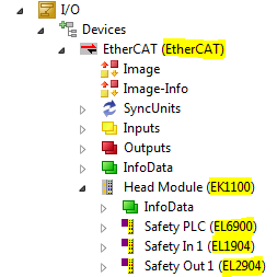
The most basic TwinSAFE system needs the Safety PLC, an input card, and an output card. These are added to your I/O bus in the typical way. Here I’ve created a small test system with an EtherCAT master, an EK1100 head module, and the three safety cards:
Adding a TwinSAFE Project
Right click on the SAFETY node in the tree in Solution Explorer and choose Add New Item… from the context menu. That will pop up the Add New Item – TwinSAFE dialog:
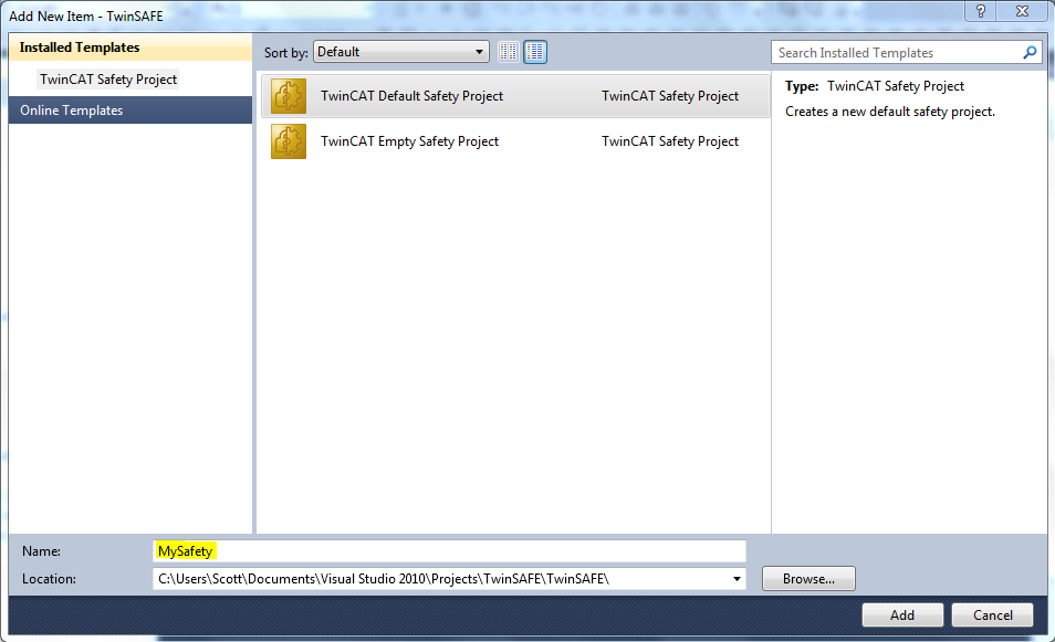
Make sure TwinCAT Default Safety Project is selected and enter a name for your safety project in the Name box (highlighted). Click Add. Now you’ll see the TwinCAT 3 Safety Wizard:
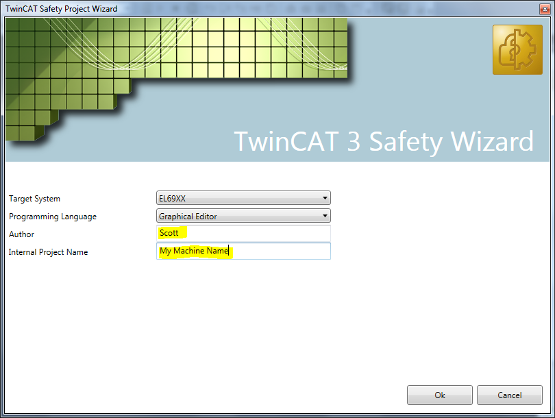
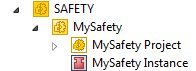
Enter your name as the Author and a descriptive Internal Project Name. Click OK. After a moment the wizard will create your new safety project:
Linking the TwinSAFE Project to the Cards
Expand the MySafety Project node so you can find the Target System node:
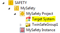
Double-click on the Target System node so you can view the EL6900 properties:
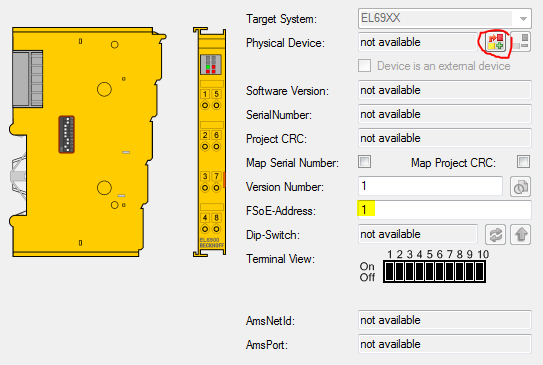
First you have to link it to the physical device (the one you added in the I/O tree). Click the link button (circled in red above). You will see the Choose Physical Terminal for Mapping dialog:
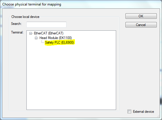
Select the EL6900 node at the bottom of the tree (highlighted) and click OK.
Each safety device in a TwinSAFE system has a unique FSoE address, and this has to be set with dip switches on the physical card. This is set in binary. Refer to the card’s documentation for how the switches map to binary values (it’s not obvious by looking at the card, unfortunately). The FSoE-Address field in the EL6900 properties page (highlighted above) has to match the dip switch setting on the card.
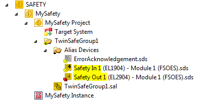
You connect the safety project to the EL1904 and EL2904 I/O cards by creating “Alias Devices” for them. In the Solution Explorer tree, below the Target System node, expand the TwinSafeGroup1 node and then expand the Alias Devices node inside the group. Right-click on the Alias Devices node and choose Import Alias-Device(s) from I/O-configuration from the context menu. That will open the Select from I/O tree dialog:
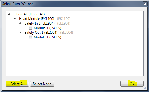
Click the Select All button and then click the OK button. It will try to read the dip switch (FSoE) addresses from each card when you import it. If you haven’t activated the configuration with the I/O in the tree, you will receive error messages telling you that you have to manually update the FSoE addresses for each alias.
Now both cards are imported as alias devices:
Setting Input Card Properties
Double-click on the Safety In 1 alias device node to edit the EL1904 properties:
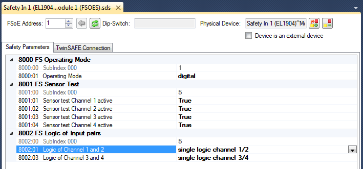
Notice the FSoE Address box at the top. This must match the dip switch settings on the EL1904 card. Let’s assume that the input (EL1904) card has an FSoE address of 2, so set that value to 2.
Now take a look at the 8001 FS Sensor Test and 8002 FS Logic of Input Pairs sections. Safety inputs are often wired in pairs, and there are different kinds of safety inputs. In all cases the system has to provide protection against short circuits and crossed channels. It does this by use of test pulses. The EL1904 can generate its own test pulses, but it can also be configured to accept test pulses generated by output signal switching devices (OSSD) such as light curtains or solid state gate switches. These parameters are used to configure what type of safety input the card should expect.
There are two very common configurations. The first is the default configuration, as you can see in the diagram above. That is, you have generation and testing of test pulses turned on (8001:01 and 8001:02 set to True) and you have 8002:01 set to single logic channel 1/2. This configuration is appropriate for all dry contact circuits, such as E-Stop buttons, mechanical gate switches, and the normally closed feedback signals from a safety relay. The EL1904 card provides a terminal that sources power to the dry contact circuit, and it automatically inserts test pulses and expects to see those same test pulses on the input. Each test pulse source is offset in time, so it can detect if someone crosses the circuits, or if the circuit is shorted to 24V or 0V.
The second common configuration is when you already have a device that outputs OSSD pulses on its outputs, so the EL1904 doesn’t need that feature. In that case, you turn off the test pulses, and configure the logic to expect OSSD pulses:
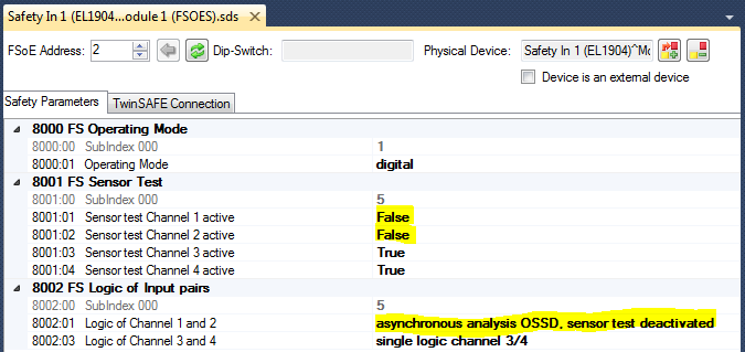
Note in the setting it refers to “asynchronous analysis”. Most OSSD devices should be outputting the test pulses out of phase with each other, so the pulses never overlap. If they do, it’s considered a fault, because that’s how the EL1904 detects crossed wires. However, there are a few OSSD devices that don’t force their pulses to be asynchronous. Ideally you should avoid these devices, but in some cases they still exist, so if you want to use them you’ll have to use the any pulse repetition OSSD, sensor test deactivated setting. This allows the test pulses to occur simultaneously.
There is a fourth setting called short cut channel 1/2 is no module fault. The EL1904 documentation is rather vague on the use of this setting, but indicates it’s needed for “safety mats”. I’m not clear on what this setting does, and I suggest contacting Beckhoff before using it for anything other than a safety mat.
In this example I’m going to describe an E-Stop function, so we can leave the default settings in the card.
Setting Output Card Properties
Double-click on the Safety Out 1 alias device node to edit the EL2904 properties:
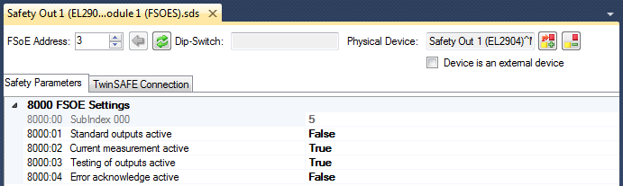
Note that I already set the DIP switch value (a.k.a. FSoE address) to 3.
The EL2904 output cards have 4 configuration parameters:
8000:01 Standard outputs active allows you to link a PLC output to a safety output, and the card will automatically “AND” the PLC output value with the safety logic output value. This allows the PLC to override an output by turning it off. In this case, the safety logic is responsible for when it’s allowed to turn on, but the PLC controls the actual timing. In my opinion you should leave this set to False and not use this feature. First of all, it’s going to make the logic more obscure, and you can achieve the same effect with an AND block inside the safety logic itself. Secondly, if you want to perform monitoring of the output in your safety logic to make sure it switches on and off when you tell it to (via a feedback circuit) then you can’t do that if the safety logic doesn’t have access to the PLC signal. Therefore it’s generally better to do this all in the safety logic, not using this “standard outputs” feature.
8000:02 Current measurement active is for monitoring a broken circuit. With this feature enabled, when the output is on, the card expects to see between 20mA and 500mA of current, otherwise the card will fault. Obviously if the device you’re turning on doesn’t draw the right amount of current, you’ll have to turn this feature off. In my experience, the feature doesn’t work very well anyway and seems to trigger falsely. That could be because the brand of relay we were using isn’t compatible with the current measurement being used. I suggest trying it, but beware that it might not work.
8000:03 Testing of outputs active is for monitoring crossed circuits, and makes use of test pulses. The card creates a train of test pulses on the 4 card outputs and makes sure that (a) the pulses don’t overlap and (b) the pulses are all different lengths varying from 300 to 800 us. These should be short enough not to interfere with the operation of a mechanical relay. In general this feature should be activated, except in cases where you are interfacing with a device that can’t tolerate test pulses. (Note that setting 8000:02 also activates test pulses, so you would have to set both settings to False.)
8000:04 Error acknowledge active controls how the card recovers from a detected output error. By default, you have to cycle power to the card to recover (typically by pulling the card out of the rack). If you change this setting to True, then you can reset it through the normal safety error acknowledgement signal configured in the TwinSAFE logic group.
Ultimately I’m trying to explain how TwinSAFE works, but I can’t make your decisions for you. It’s your responsibility to understand the impacts of these settings and design your system to meet the safety requirements of your specific application.
The TwinSAFE Group
When you created your TwinSAFE project, the wizard automatically created a TwinSAFE “group”. The groups are a way to logically separate your safety programs. For instance, let’s say you have two physically separate work-cells both controlled by the same TwinSAFE EL6900 safety PLC. Since they’re logically two distinct machines, it makes sense to separate the logic into two separate TwinSAFE groups.
The purpose of the groups is to manage error reactions. When a safety malfunction is detected, such as an output card fault, a communication fault with one of the cards, a discrepancy between the two channels of a two-channel input device, or a detected failure of a safety relay via a normally closed feedback circuit, then the entire group enters a faulted state, all of the outputs revert to their “safe” state (i.e. “off”), and the fault must be acknowledged with the error acknowledgement signal. In the case where you have two physically separate machines controlled from the same safety PLC, it makes sense to separate them into two groups so that a safety device malfunction on one machine doesn’t cause the other machine to stop.
The TwinSAFE Group Properties
When the wizard created your TwinSAFE group, it also created the first alias, called ErrorAcknowledgement. This is supposed to be linked to a PLC output or a standard input (such as a pushbutton) and used to acknowledge safety group errors. Linking standard variables is always a 2-step process: first you have to link from inside the logic to the alias, and then from the alias to the PLC or physical I/O.
Start by opening the safety application called TwinSafeGroup1.sal by double-clicking on it in the Solution Explorer tree. That opens a blank TwinSAFE application:
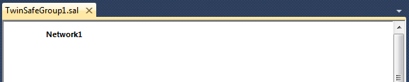
Not very exciting, I admit. The trick is, you now have to right click on the background and choose Properties from the context menu. This opens the properties tool window:
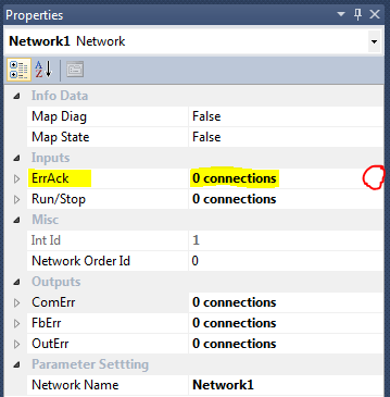
You have to link the ErrAck signal (highlighted) to the ErrorAcknowledgement alias variable that the wizard created for you. Click on the spot shown by the red circle, above, and you should see a “…” button. Click on that button to open the Choose Alias Port dialog box:
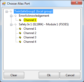
Select the highlighted node (Channel 1 under ErrorAcknowledgement). Now the properties will show that you’ve linked the signal:
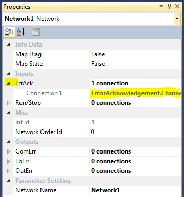
You should also link the ComErr (communication error) and FbErr (function block error) outputs. These are diagnostic outputs which tell you that there’s an error either in a connection (from the EL6900 to one of the EL1904/EL2904 cards) or in a function block (such as a two-channel discrepancy error), respectively. Start by creating two output aliases. Right click on the Alias Devices folder under the TwinSafeGroup1 folder in the Solution Explorer tree and select Add->New Item… from the context menu. That will open the Add New Item dialog:
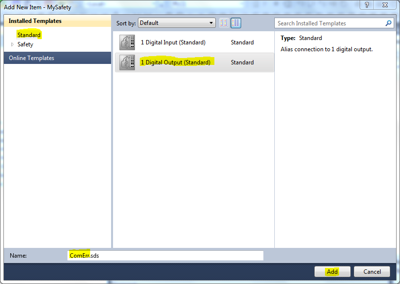
Select Standard from Installed Templates in the top left corner. Select 1 Digital Output (Standard) in the center box, and then enter a name (ComErr.sds) in the Name box. Finally, click the Add button. Now you’ll see the ComErr standard output alias device added:
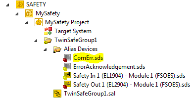
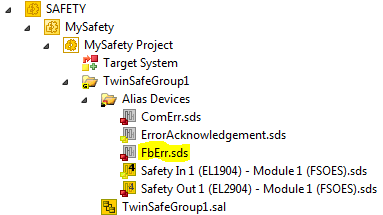
Repeat the process to add an FbErr output alias device:
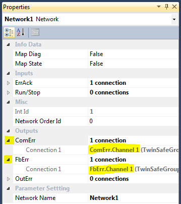
Now go back to the TwinSAFE Application Properties tool box and link the ComErr and FbErr outputs to your new aliases:
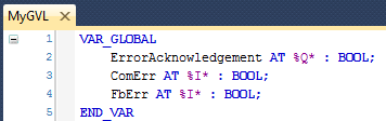
Now we have to link these standard input and output aliases to the PLC. I’ve created a GVL in my PLC project with the following 3 variables defined:
Right click on your PLC project and build it, so that you can link these variables. Standard input and output alias variables can only be linked from the alias itself. Double-click on the ErrorAcknowledgement.sds alias in the Solution Explorer tree:
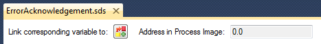
Click on the link button, and link it to the MyGVL.ErrorAcknowledgement output from the PLC. Now do the same thing for the ComErr and FbErr aliases to connect them to your PLC.
Whew! Now we’re ready to start writing some safety logic.
Writing Safety Logic
Double-click on the TwinSafeGroup1.sal safety application in the Solution Explorer tree. What you see is a blank safety application:
The wizard automatically created the first “network” for you. The safety program is written in the function block diagram (FBD) language. The program is broken up into “networks” (think of them like rungs in a ladder logic program). Start by renaming Network1 to EStop. Click on the existing network name to select it and start typing the new name, and press enter when complete.
Now you need to start adding function blocks to the network. Available safety function blocks are in your Toolbox window. Use View->Toolbox from the main menu:
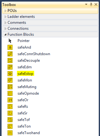
Now click and drag the safeEstop function block (highlighted) and drop it in your network:
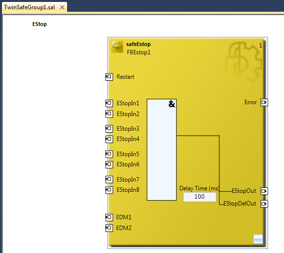
The safety function blocks are certified safety function blocks. The combination of the function blocks and the hardware platform (the EL6900) makes them suitable for use in a safety application.
This block can monitor up to 4 two-channel e-stop circuits. If any of the EStopInN safety inputs turn off, then the EStopOut safety output will turn off immediately and the EStopDelOut safety output will turn off after a programmable delay (see the Delay Time (ms) box). To turn the EStopOut and EStopDelOut outputs back on, the function block needs to see all enabled EStopInN inputs on, and needs to see a 0->1->0 transition on the Restart input.
The block has optional EDM1 and EDM2 “electronic device monitoring” inputs. EDM1 corresponds to the EStopOut output and EDM2 corresponds to the EStopDelOut output. If EDM1 is enabled, then the EDM1 feedback input must be on prior to the 0->1->0 transition on the Restart input. Assuming the EStopOut output is connected through an EL2904 output card to turn on a pair of force-guided relays, then the normally-closed contacts of both relays should be connected in series to the EDM1 input of the function block. In the event that one of the force guided relays fails to switch off, this feature will prevent the safeEstop block from restarting, preventing the system from operating.
Start by adding a two-channel e-stop circuit to inputs EStopIn1 and EStopIn2. Start by single-clicking on EStopIn1 to select it, then right click on it and select Properties from the context menu:
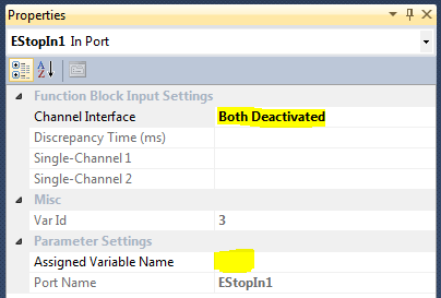
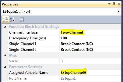
Note that EStopIn1 and EStopIn2 are an “input pair” and can be configured to monitor both inputs together. That’s what we want in this case, so in the Channel Interface property, select the Two-Channel setting. Now under the Assigned Variable Name property, type in a descriptive variable name for this variable. I suggest EStopChannelA:
These changes are reflected on the function block as well:
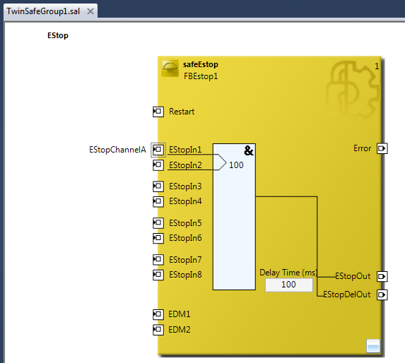
As you can see, the EStopIn1 and EStopIn2 inputs now have lines under them indicating they are activated, and there’s also connecting lines between them inside the “AND” block with 100 indicating the block will monitor that the two inputs switch within 100 ms of each other. If they don’t, this is considered a function block error, so it will turn on the Error output, and it’s also a group error so all outputs in the group will turn off and you will need to send a 0->1->0 transition on the ErrAck group input to reset.
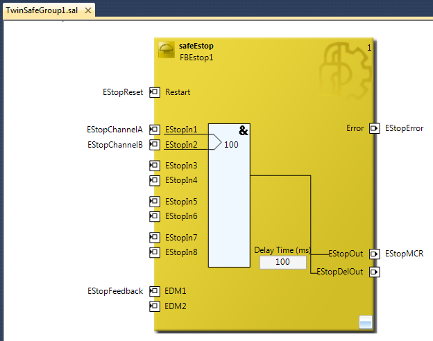
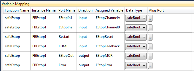
Now configure the EStopIn2 input with variable name EStopChannelB. Similarly, configure the Restart input with a variable name of EStopReset, the EDM1 input with variable EStopFeedback, the EStopOut output with variable EStopMCR (“MCR” meaning “master control relay”), and finally the Error output with variable EStopError:
Link the TwinSAFE Variables
We declared the variables in our safety program, and now we have to link them to our Alias Devices. There should be a tab at the bottom of your screen called Variable Mapping. If you can’t find it, try going to View->Other Windows->Variable Mapping. This is where you link your safety program variables to aliases:
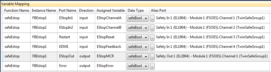
Clicking the “…” button in the right-most Alias Port column brings up the Choose Alias Port dialog box, just like when you linked the ErrAck, ComErr, and FbErr group I/O to the Alias Devices earlier. In this case you’re going to be linking the safety variables to the EL1904 and El2904 safety I/O cards. Go ahead and link all but the EStopError variable to the Alias Devices:
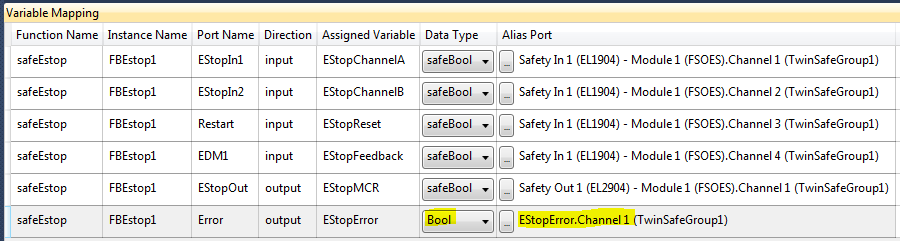
The EStopError variable is a diagnostic signal, not a real safety output. We really just want to send that signal back to our PLC so we can display a fault message or show it on the HMI. First, create another standard output variable alias device called EStopError.sds (the same as you did for ComErr.sds and FbErr.sds previously). Second, use the drop-down box in the Data Type column to change the data type from safeBool to Bool (a safeBool can only be linked with safety I/O and a Bool can only be linked with standard variables). Third, link the EStopError variable to the EStopError.sds standard output alias:
Finally, you’ll need to create another input variable in your PLC (EStopError AT %I* : BOOL;), build your PLC project, double-click on the EStopError.sds alias, and use the link button to link it to the PLC I/O.
Downloading to the EL6900
Start by doing a safety “verification”. This is like a “build” or “compile” in that it checks for errors. In the case of TwinSAFE, it checks for things like inputs or outputs not connected to alias devices, or inputs on function blocks that are enabled and not connected to variables. From the menu at the top, select TwinSAFE->Verify Safety Project (Project Level). If successful, it will display the message Verification Process succeeded in the status bar at the very bottom of the window.
If you don’t have any hardware connected, then this is as far as you can go. Everything else requires you to have a working EtherCAT master with all your I/O connected and communicating. This requires a typical “activate configuration” as well.
If you do have the hardware connected, select TwinSAFE->Verify Complete Safety Project (Project and Hardware Level) from the main menu. This does a similar verification but it also checks that the DIP switches on the physical I/O cards match the settings in the alias devices, etc.
If that verification is successful, then you can select TwinSAFE->Download Safety Project from the main menu. That’s going to pop up a dialog box asking you for 3 things:
- Username
- Serial number
- Password
The default user name is Administrator. The serial number refers to the EL6900’s serial number. You can find it on the card itself, or you can also find it by double-clicking on the Target System node under the safety project in the Solution Explorer tree. The default password is TwinSAFE (note that it’s case sensitive). Once you put the system into production, this password should be changed and kept in a safe place, typically with the safety audit documentation.
Once you enter these fields and continue, it will then display a download screen where it downloads the function blocks to the EL6900. When the download is complete, you have to enter the password one more time to activate the download, which allows the EL6900 to run the safety program.
Going Online
First, go online with your PLC project and look at the signals from the safety PLC. You should see that you have a communication error (or ComErr). To reset the communication error, it needs to see a 0->1->0 transition on the ErrorAcknowledgement signal.
Second, you can go online with the safety PLC. Double click on the safety group to display the safety program, and then select TwinSAFE->Show Online Data of Safety Project from the main menu. Now you’ll be able to monitor the online value of the variables, and see the state of the function blocks. There is also a small window or tab at the bottom of your screen called Safety Project Online View. Once you’re online, open this window and you can get more information about diagnostic signals from each connection and each function block.
Additional Function Blocks
The EL6900 supports more than just the safeEstop function block. There is a document published by Beckhoff listing all the function blocks. The document is titled “Function Blocks for TwinSAFE Logic Terminals”, and is available from the TwinSAFE Product Documentation page.
Connections Between Function Blocks and Networks
You can connect an output on one function block to an input on another function block by just clicking and dragging a connecting line between them. For example:
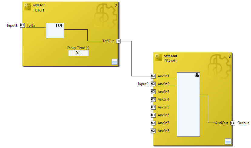
If you have a hard time getting your mouse to start the link or end the link, then try using the zoom feature to zoom in first, and that will make it easier to hover your mouse over the right link spot. This is even more important if you have a single output branching out to multiple inputs.
Let’s say you have a function block in one network and you want to connect an output from that block to an input on a function block in another network. You can do this by typing in a fully qualified address of the other point using the syntax: Network.FunctionBlockName.InputName. For example:
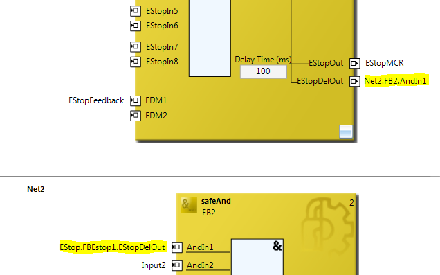
Monitoring in the PLC
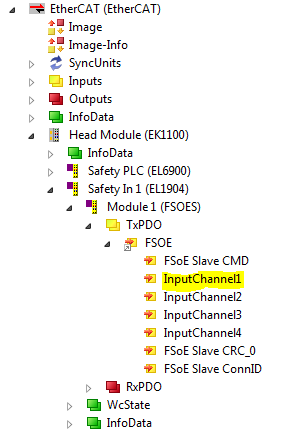
TwinSAFE provides the reliability you need to meet the safety requirements of your machine, but you still need to make the operator interface user-friendly. Typically this means bringing status signals into your PLC and using that to create faults and alarms. I’ve already described how to bring the error signal from a function block out to an alias device and link it to a PLC variable. You can also link PLC I/O directly to the safety I/O in the I/O tree in the Solution Explorer. For instance, here’s where you can link a PLC input to an EL1904 safety input:
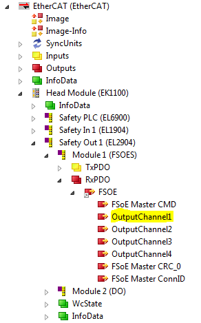
Here’s how you link a PLC output to an EL2904 safety output:
Conclusion
That’s it! Obviously safety is a big topic and TwinSAFE is necessarily complicated by its stringent requirements. Overall, the TwinSAFE system can be a cost-effective way to implement a safety system, and it provides excellent integration into the rest of the PLC control system which makes monitoring and diagnostics much simpler.
This chapter is part of the TwinCAT 3 Tutorial. Continue to the next chapter: The Scope View.