The Input Map pattern is an under-used and valuable Ladder Logic Programming Pattern. The logic itself is simple:
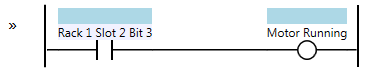
Input Map
In most traditional PLCs you refer to an input by its physical location in the I/O structure. For instance in an Allen-Bradley SLC500 processor, I:4/0 would mean input slot 4 bit 0. You are encouraged to create a descriptive comment for this bit so you can easily see what’s connected to that input.
With the introduction of the ControlLogix/CompactLogix line of controllers, two things happened. First, the actual input name got much longer: Local:4:I.Data.0 means the same as I:4/0 in the SLC500. Second, the inputs now update asynchronously to the program scan. Let me show you what that means:
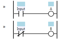
Asynchronous Inputs
In these two lines of ladder logic, we use one normally open (N.O.) contact from an Input to energize coil A, and a normally closed (N.C.) contact from the same Input to energize coil B. You might make the assumption that coil A and coil B would never be on simultaneously during the same program scan, but if your PLC has asynchronous inputs, you would be wrong. Since the input scanning is done asynchronously to the program scan, the Input can actually change state between the time when the first rung is solved and the second rung is solved. This is a very insidious problem because it’s very rare for it to happen, but it’s possible. That makes it a potentially very difficult problem to debug.
These features of the ControlLogix/CompactLogix PLCs make the Input Map pattern fairly common. Many PLC programs have a routine at the beginning called “Map Inputs” that take the raw physical input as a contact and use it to drive an internal relay coil. The internal relay coil is then used everywhere else in your program, and the Input itself is only used once, in this one spot.
The Input Map pattern has several other advantages beyond synchronizing your inputs to your program scan. For instance, PLC inputs can and do fail from time to time. Most machines have spare inputs, so rather than replacing the input card (which is expensive and may not be possible if you need to fix it immediately), a technician will typically just move the wire to another input. This means they have to change the logic to use the new input everywhere it’s used in the program. Some inputs are only used once or twice, but some might be used dozens or even hundreds of times (imagine a fault reset button, for instance). If you use the Input Map pattern, you only have to change the program in one place.
Likewise, you can combine the Input Map pattern with the Debounce pattern. If you find that you’re having a problem with contact bounce or electrical noise on an Input, then having the Input Map pattern already in place means you now have a single place to add the Debounce logic without affecting the rest of the program.
Furthermore, on PLCs that support tag names rather than direct memory addresses, you can map the input to a more descriptive tag name than the physical location where the input is connected. You can also map the input to a shorter more compact tag name (like I04.0) which is much easier to fit on a wire label than Local:4:I.Data.0.
Use of this pattern is PLC-specific. For instance, Beckhoff’s TwinCAT PLC software already includes an I/O mapping function, so you map internal variables like MyMachine.MotorRunning to a physical input using their System Manager. Their I/O scan is also synchronous to the program scan, so there are fewer advantages to using the Input Map pattern with Beckhoff TwinCAT systems.
More Patterns of Ladder Logic Programming.
Thank you for sharing your knowledge. Your site is awesome and much appreciated.
I develop on Beckhoff’s TwinCAT 2 and TwinCAT 3 platforms, and I must say that it is very refreshing to see that others are taking the same approaches to problems like IO mapping.
I have developed hardware interface routines which are identical to what you described here. Regardless of whether your IO is updated synchronously or asynchronously, I would argue that this is the best method for handling IO because it scales beautifully as your system grows and changes. It also allows you impose logic on internal IO variables. For example, InternVar = Local:4:I.Data.0 XOR Local:4:I.Data.1; which would effectively bottleneck both hardware inputs before InternVar is set throughout your program. Otherwise, you will need to repeat the same type of logic throughout your program–which makes your program very difficult to change at a later time. In my experience this is not only the smartest way to go, this is the only way to go if your platform allows you to do so.
Pingback: How to Write a Big PLC Program · Contact and Coil
There is another advantage of mapping inputs:
Disable the mapping so you can simulate the inputs and test your program.
Similar to mapping outputs. If you want to test your program without turning on the actual hardware you can disable the mapping of the outputs.
Another PLC that has their I/O scan synchronous to the program scan is Siemens.
King regards, Daniel