Perhaps the most controversial Ladder Logic Programming Pattern is the Five Rung Logic block. The purpose of the pattern is to encapsulate all the elements required for a single machine “motion”. The idea of what constitutes a motion is a little vague, but it’s generally the following:
- The PLC does something to initiate a motion (like turn on a valve or tell a robot to move)
- There is some kind of signal to indicate the motion is complete (such as a sensor)
- We want to monitor the time it takes to complete and generate a fault if it takes too long
As you can imagine, a lot of machine control can make use of this pattern. Any time you have an air cylinder with feedback sensors (extended/retracted) then you can throw two five-rung logic blocks in there. You can also use it when you have to command a motion controller or a robot to move one or more axes to a given position.
The Five Rung pattern is called that because there are 5 coils typically used:
- Precondition (aka Trigger)
- Safety
- Command
- Complete (aka “In Position”)
- Fault
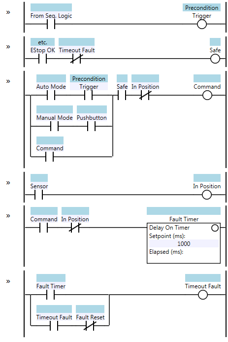
Five Rung
Some variants of this pattern would put the Safety rung before the Trigger rung, but I like to reverse that because the Trigger rung really indicates when the motion starts. In a typical program, if you’re using the Step pattern, then the trigger will be driven by a Step In Progress contact. Note that in a more complicated program this motion might be initiated by many different steps in your sequence, so you just put a bunch of Step In Progress contacts in parallel here. In a program that doesn’t use the Step pattern, then the Trigger coil could be driven directly by logic like some other cylinder extended and a part present input on. It’s important to realize that the Step pattern is more scalable and better for larger programs, but it’s not the only way to do it.
The Trigger coil only has to be on to initiate motion and only works if the machine is in Auto Mode. The Trigger coil doesn’t have to stay on the whole time. In some cases it might be common to put the motion complete sensor in this rung as a normally closed contact, so that the motion won’t initiate if the axis is already in that position. That’s redundant in our case because we take care of that later, as you’ll see.
The Safety rung is a set of conditions that have to be true during the entire motion. The prototypical example is “all E-Stops OK” but other conditions you would see here are signals from interfering axes. For example, let’s say that you have two cylinders, A and B, and only one of those can be extended at a time. It’s typical to put the Cylinder A Retracted sensor (and the Cylinder A Extend output) in the Safety rung for the Cylinder B Extend Five-Rung block, and vice-versa. This is a good double-check of your logic, so even if you make a mistake in your sequence logic, at least you’ll prevent the two cylinders from crashing into each other.
The Command rung acts as the memory in this pattern. It remembers that we’re trying to perform this motion. It can be initiated in Auto Mode by the Trigger signal or in Manual Mode by a button or other manual control. Note that the Safety conditions still have to be met even in Manual Mode, so we don’t risk allowing the operator to crash the machine inadvertently. Once the Command coil turns on, it seals itself in, typically until the motion is complete, but alternatively the circuit will be broken if the Safety rung drops out, which is basically an Abort.
Note that the example above shows an “Auto Mode” signal but you will typically see this replaced with an Auto Cycle Running signal, since most machines require you to put the machine into Auto Mode and then initiate a cycle with another button. Sometimes this is captured in the Command rung, and sometimes this is done in the Trigger rung.
The In Position rung is responsible for figuring out how you know that the motion is complete. If you have a sensor, you can use that. If you have a Motion Complete signal coming back from a motion controller or a robot, you can easily use a rising edge detection on that signal as well (in this case I would call this a Complete rung, not an In Position rung). It may also be common to put a timer in this rung to “make sure” that the motion really is complete before we do whatever is next. I prefer not to use timers unless I have some kind of nuisance problem with the machine, but I’ve seen some logic where there’s a timer in every single In Position rung. The problem with timers is that they slow down your cycle time, and nobody wants that. Note that it’s a good idea to use the In Position coil as the canonical indication that this axis is in this position. By that I mean if other parts of your program need to know that your cylinder is in the Extended position, it’s better to use this In Position coil rather than using the inputs themselves. That gives you a single place to change your logic if, for instance, you have to move the sensor to another input due to a blown input, or you want to add a timer due to “bouncing”. If you’re using the Step pattern, it’s typical to use the In Position signal in your Step Complete rung.
The next two rungs, together, make up the Fault rung and you may sometimes see them combined into a single rung depending on the programmer’s preference. The Fault rung implements a simple Timeout Fault for the motion. If you’re trying to extend a cylinder, and it takes more than a second, chances are there’s a problem. This is an example of the State Coil pattern, and requires the operator to reset the fault to continue. It’s important that this fault be reported to the operator to indicate which motion was causing the problem. Note that it also drops out the Safety rung to abort the motion. This is optional, but generally a good idea because it’s possible that the axis or cylinder is jammed and you want to stop trying to move it to prevent further damage to the machine. It isn’t always the case that you want to stop the motion, so use your judgement.
In my programs I’ll typically use a three level system of ladder logic patterns:
- Highest level: the Mission pattern
- Middle level: the Step pattern
- Lowest level: the Five Rung pattern
For example, a Mission might be “Pick Up Part”. Then there will be a routine with all the Steps necessary to perform a pick-up-part sequence, such as “Extend Arm and Turn on Vacuum”, “Extend Gripper”, “Verify Suction”, “Retract Gripper”, “Retract Arm”. Then I would have several low-level routines, such as “Arm”, “Gripper”, and “Vacuum”. The Arm and Gripper routines would each have two Five Rung logic blocks in them, one for Extend and one for Retract. The Vacuum isn’t really a motion, so it would have simpler on/off type logic, and some kind of vacuum sensor feedback logic in it.
I should warn you that when someone first sees a Five Rung logic block, they usually ask, “why do you need so much logic just to turn a valve on?” Well, that’s the difference between an experienced ladder logic programmer and an inexperienced one. Eventually the inexperienced programmer will write some really simple and straightforward logic to turn the valve on and off, and then they’ll have to add some kind of fault when the cylinder motion doesn’t complete (or the sensor stops working), and then they’ll have to differentiate between how it operates in Manual Mode instead of Automatic Mode, and before they know it they’ll have created their own custom version of a Five Rung logic block. In their next program they’ll probably just do it this way.
More Patterns of Ladder Logic Programming.
Excellent example, but I more often see E-stop as normally closed rather than (E-stop OK) as normally open. Logically they are the same, but in the physical world implemented with relays and contacts E-Stop as normally closed means you are getting a signal through your e-stop circuit.
Would you recommend using this pattern, or a variant there-of for registration? The sensor input being driven by the detection of the registration mark, and the fault being a position/time window, within which, that mark should be?
@BrandonFarmer – Yes, I generally use this pattern for a “Home” or Referencing motion for a servo. When the command bit is on, I initiate the MC_Home (or equivalent) function block, which starts the referencing motion. In that case, the In Position rung turns on when the Axis.Homed status bit turns on. The pattern is useful here because it gives you a timeout fault, and a Safe rung where you can put anything that needs to be clear before it can home. Note that if the Command bit drops out without you successfully reaching home (because the Safe rung dropped out) then you need to call MC_Stop to abort the homing procedure and make the axis stop.
Are there any variant for this with fault handling if the contactor fails to turn off?
@Max – this pattern doesn’t include the means of actuation. So, how you turn the command into an action (turning on a contactor) and the fault monitoring associated with that actuator (feedback monitoring of the contactor) belongs in its own section. The command bit, above, could drive the coil, and you could use the State Coil / Fault Coil pattern to detect a faulted contactor.
Eliot Ayres comment on the field wiring of the E-stop accurately describes the fail-safe nature of the hard-wired circuit, however it should be noted that the
E-stop signal input to a standard (non-safety rated) PLC should never be used for safety purposes. With that point in mind it is customary to use the E-stop
input as shown in the diagram. The purpose of the E-stop input is to coordinate the action of the PLC program with the external hard-wired safety circuit so the PLC program “behaves” appropriately during the E-stop event, and to facilitate a graceful program recovery once the E-stop is reset. Standard PLCs should never be used as the final safety element in any design, including, but not limited to E-stops and Anti-Tie down circuits.
Hello Scott,
How would you modify this 5-rung pattern if you DIDN’T have a sensor to denote the motion is complete? Or rather, let’s say we want to control a pump, maybe a flow sensor could provide the feedback or even a level sensor in a tank attached to the pump circuit, would it make sense to use the 5-rung pattern in this same way? Or would you recommend a different approach?
@MattVarney: This pattern is really meant for the control of movement with some kind of feedback, so I wouldn’t normally use it for a pump. A pump is either on or off, or maybe it’s off, starting, on, stopping, etc., but it doesn’t really move from one point to another.
As for movement without a feedback sensor… if I only have one sensor, like “retracted”, then the extended five-rung typically uses the “not retracted” condition with a delay-on timer. If there are no sensors at all, then I’d just use the output and put it through a timer. The fault rung is pretty useless in that case, but at least you get the rest of the rungs, and who says someone won’t add a sensor later?