This chapter is part of the TwinCAT 3 Tutorial.
This “Quick Start” is actually rather long, but it’s going to take you through downloading, installing, configuring, programming, building, activating, going online, forcing, and even making online changes to a TwinCAT 3 PLC program. When you’re done you will have a basic understanding of the TwinCAT 3 system and how it works.
Prerequisites
TwinCAT 3 can run on a plain-vanilla copy of Windows 7. As of June 2016, Beckhoff says TwinCAT 3 is fully supported on Windows 10 (with TwinCAT version 3.1.4020.0).
One of Beckhoff’s main product lines is industrial PCs and if you buy their industrial PCs, you’ll get a discount on the TwinCAT 3 license. Also, the license cost scales with the processing power of the PC. Their most expensive license tier is for “3rd party hardwareâ€, which means any PC you didn’t buy from them. I have no opinion on whether you should buy a Beckhoff industrial PC or a commercial PC. One thing to keep in mind is that Beckhoff’s top of the line industrial PC won’t have quite as much processing power as the newest commercial PCs on the market today, so if you’re really concerned about performance, you’ll probably go with a commercial PC. On the other hand, industrial PCs are hardened against tougher environmental conditions like dirt and temperature, and they come in nicer form factors for mounting inside of a control panel. They also take a 24V input rather than running from the AC mains. Whatever you do, make sure you invest in a good UPS as well.
BIOS Settings
If you use a 3rd party PC, you may have to change the following settings in the BIOS:
- Turn off Hyper-Threading (Intel Core-i7 specifically)
- Turn on Intel Virtualization Technology Extensions (VT-x), which is required for the 64-bit version of TwinCAT 3
Optional: I/O
Whether or not you’re hooking up to a legacy system, or starting fresh, I highly recommend using an EtherCAT I/O bus. The performance is phenomenal compared to any other bus on the market today, including any other Ethernet-based technology, and even SERCOS. The price is also quite reasonable because the technology is based on commodity Ethernet hardware.
If you do want to go with EtherCAT, you can’t just use any Ethernet card in the PC as your bus master. It has to be an Intel chip, as that’s the only chipset that Beckhoff’s EtherCAT bus master seems to support. While you can buy a compatible card from Beckhoff, I’ve also had success with commercial off-the-shelf Ethernet cards. Your mileage may vary. For a list of compatible Ethernet chips, do a Google search for beckhoff ethercat compatible cards or visit the following URL: http://infosys.beckhoff.com/english.php?content=content/1033/tcsystemmanager/reference/ethercat/html/ethercat_supnetworkcontroller.htm
As of this moment, an Intel Gigabit CT PCI-E Network Adapter EXPI9301CTBLK is a reasonably priced commodity card that works well (Note: as of April 2018, I no longer recommend these cards. There seems to be some issue with these cards and the Beckhoff EtherCAT driver. Replacing them with FC90xx cards from Beckhoff resolved our problems).
If you want to try TwinCAT 3 without any hardware attached, you can do that too, and you won’t need an EtherCAT master at all.
If you do happen to need to interface to legacy I/O buses like DeviceNET, rather than installing a DeviceNET bus master card in the PC itself, I highly recommend starting with an EtherCAT bus to an EtherCAT bus coupler such as an EK1100, and then buying one of the many different EtherCAT-to-whatever bridges that Beckhoff sells, as this is usually less expensive in the short run, and lets you expand your system with lower cost (and higher performance) EtherCAT I/O in the future.
Optional: Visual Studio 2010 Professional
If you’re already a .NET programmer then you may already have Visual Studio 2010 Professional installed. If that’s the case, TwinCAT 3 will actually install as an extension to VS2010. If you don’t have it installed, don’t worry; TwinCAT 3 will install the Visual Studio Shell instead.
You may wonder if you can use the free versions of Visual Studio such as Visual C# 2010 Express edition or Visual Basic .NET 2010 Express Edition. While you can have them installed, and you can use them to write programs that communicate with the TwinCAT 3 runtime, TwinCAT 3 won’t install as an extension to these products.
Downloading TwinCAT 3
The TwinCAT 3 installer is free to download, but it requires registration. Beckhoff periodically releases new versions, so to get the very latest, go to their product web page:
http://www.beckhoff.com/english.asp?download/tc3-downloads.htm
Click the TE1xxx | Engineering link under the Software section. Click on the TwinCAT 3.1 – eXtended Automation Engineering (XAE) link. Note that XAE includes the runtime (XAR) as well.
Once you register you’ll receive an email with download instructions. Download the .zip file and extract it to some temporary directory.
Installing TwinCAT 3
In the directory where you unzipped the downloaded TwinCAT 3 archive, locate the “exe” file and double-click it.
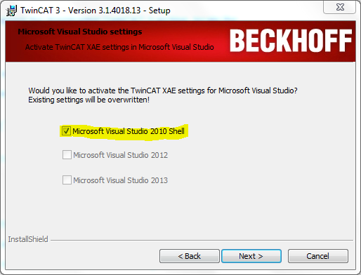
Follow the directions. Use the default options. When it prompts you about the Visual Studio 2010 shell, check the box to install it:
You will have to restart before it completes.
Create Your First TwinCAT 3 Project
Now that you have TwinCAT 3 installed, check in your system tray for a new icon:
![]()
Just for reference, the color of the icon (blue) means the TwinCAT 3 runtime (PLC/motion controller/etc.) is in Config mode. That’s similar to “program mode†on an Allen-Bradley PLC. When the runtime is started the icon will be green. Red means it’s stopped.
Right-clicking on the icon will display a system menu:
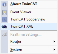
Select TwinCAT XAE from the system menu. (The “E†stands for “Engineering.†That’s the programming environment.)
After the splash screen you’ll see the Visual Studio Start Page:
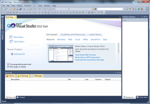
Click the New Project… link (highlighted) on the left side of the page. That will display the New Project dialog:
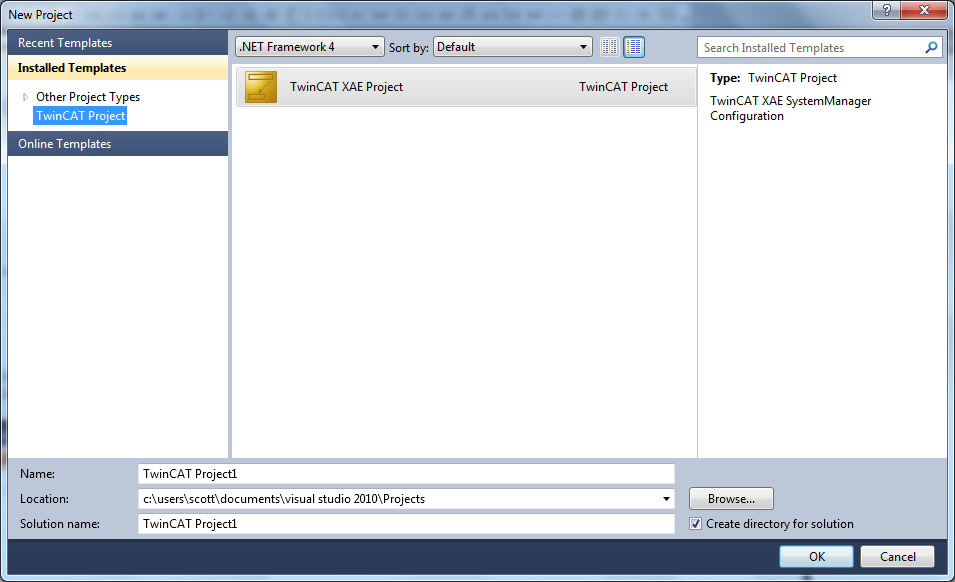
I’ve only installed TwinCAT 3 without installing Visual Studio 2010 Professional, so you can only see one project type: TwinCAT XAE Project. If you have Visual Studio 2010 Professional installed, you’ll see all the regular project types, plus this new TwinCAT XAE Project type. Make sure you’ve selected this type. Then give your project a suitable Name (see the highlighted field above). When you change the project name, the solution name will change to match. For our purposes they can be the same name. I chose “TwinCAT 3 Tutorial.” Click OK.
This could take a minute. It’s building a new TwinCAT 3 project from a template. When it’s complete you’ll see a screen like this:
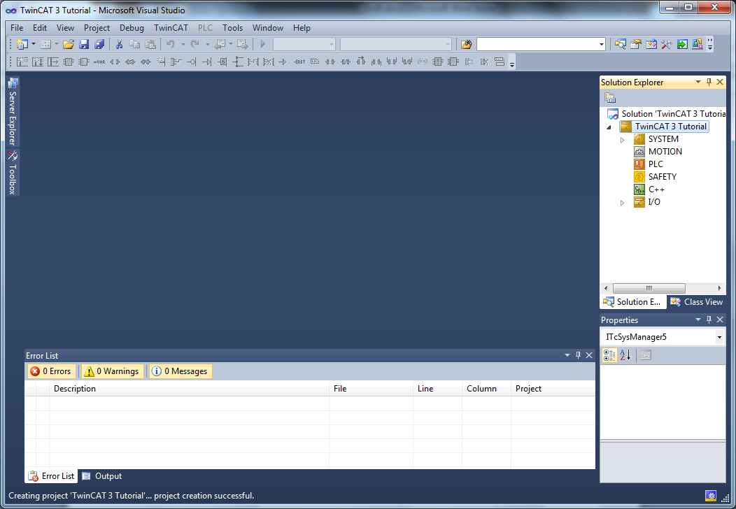
All of the files for this project are organized in the Solution Explorer on the right. Here’s a brief explanation of each section:
The top node in the tree is the “Solution.” This is actually a Visual Studio construct, not a TwinCAT 3 object. In Visual Studio, a Solution is a group of Visual Studio Projects and an associated “build order.†In our case there’s only one Visual Studio Project: TwinCAT 3 Tutorial. If you’re using Visual Studio 2010 Professional, you would be able to add additional projects under the solution, such as a C# or VB.NET project (perhaps an HMI or a data collection application?). This would be convenient simply because you could keep everything in one place and even use the integrated source control add-ins to manage everything in one environment.
Under the project you have:
- SYSTEM: this section manages the runtime including the licenses. You can configure how many PC processor cores to use, which PLC or motion tasks run on each core, and what percentage of each core’s processing power to allocate to each task. Note that it’s possible to connect to runtimes on other computers, but for now we’ll only be concerned with the local runtime.
- MOTION: this is where you add motion control tasks, and assign axes to each task. These tasks do the work of closing the control loops for you. Your PLC programs typically interface with the motion tasks using standard motion function blocks and the motion tasks do the heavy lifting of controlling the actual servo drives, etc. When you commission a new axis (setting up your motion parameters like speed, acceleration, deceleration, etc., you interact directly with the objects under the MOTION section of the tree).
- PLC: this is where you add PLC projects. Each PLC project lets you define variables (memory assignment) and PLC logic.
- SAFETY: if you’re using an EL6900 Safety PLC slice or the new TwinCAT 3 safety runtime (a certified safety PLC that runs on the PC itself), you can edit the safety logic here. This is handy because you can create connections between the PLC and the Safety logic for monitoring and status.
- C++: one of the big new features or TwinCAT 3 is the ability to write C++ code that executes directly in the runtime.
- I/O: this is where you configure your I/O network, and then create your mappings between all of the different modules. For example, if you define an input in the PLC module, you have to map it to a physical input in the I/O module.
TwinCAT 3 Solution File Structure
One of the interesting things about TwinCAT 3 compared to other PLC programming environments is that it stores the “solution” in a collection of files and directories rather than in a single monolithic file. If you open the directory where you asked it to create your solution, you’ll see the following:
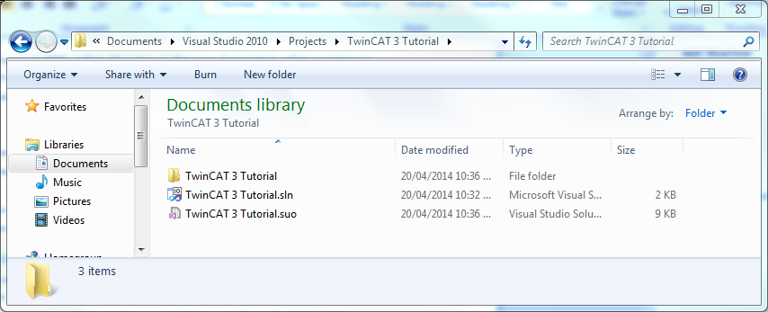
The TwinCAT 3 Tutorial.sln file is your “solution” file, and it corresponds to the top level node in your solution explorer in the right hand side of your TwinCAT XAE window. The TwinCAT 3 Tutorial folder corresponds to the TwinCAT 3 Tutorial project under the solution. If you double click on that folder, you’ll see a file called TwinCAT 3 Tutorial.tsproj:
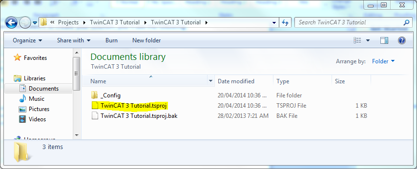
If you’re inquisitive, you can open this file with Notepad (or any text editor) and look at the contents. You’ll see that it’s just an XML file. When you start to add a PLC program or a Safety program in the editor, you’ll then see new folders created here, and the TwinCAT 3 Tutorial.tsproj file will include references to these child projects.
Adding a PLC Project
In TwinCAT 3, a “PLC” is like a “virtual” PLC. You can run multiple virtual PLCs on a single computer. This might actually be useful if you had a single PC controlling multiple machines. Each machine could be controlled by a single virtual PLC, which might be a good way to manage the complexity of a large system. You can also separate virtual PLCs by CPU core, so if your scan time started to get too high, you could break out part of that logic and run it in a separate virtual PLC and schedule the task that runs that second PLC on a different CPU core. Two virtual PLCs can still send data back and forth by mapping outputs on one PLC to inputs on the other PLC, and vice-versa.
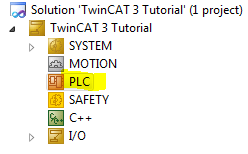
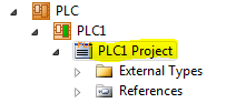
The simplest case is to create a single PLC project. Let’s do that now. Right-click on the PLC node in the Solution Explorer (highlighted):
From the context menu that appears, select Add New Item… to display the following wizard:
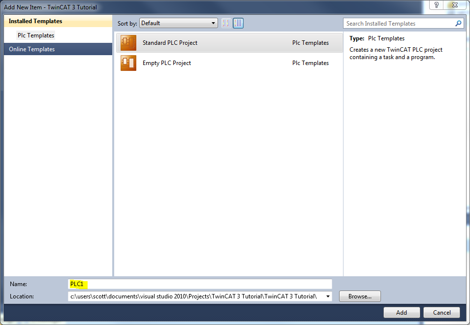
Enter a name for your new virtual PLC in the Name box (highlighted above). I chose “PLC1” but you may want to pick a more descriptive name, like the name of the machine or cell that this PLC will control.
Standard PLC Project is the default template, so leave that selected and click the Add button in the bottom right. TwinCAT 3 will build a new PLC project for you from a template. This could take a few seconds to a few minutes depending on the speed of your computer. When it’s complete, you’ll see your new PLC in the Solution Explorer:
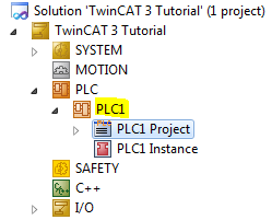
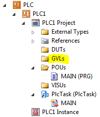
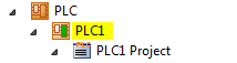
It gets a little confusing to talk about the “PLC Project” now because there are so many nodes in the tree, so from now on I’ll call the nodes by their name: PLC1 or PLC1 Project.
Most of the interesting parts are under the collapsed PLC1 Project node, so click on the triangle next to that node to expand it:
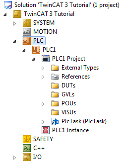
Let’s go through them one at a time to explain their meaning:
- External Types: you should never have to go in here, so don’t worry about it.
- References: this is where you add references to external libraries (either ones that are included in TwinCAT 3, such as motion control libraries, or ones that you write yourself, which we’ll explain later).
- DUTs, GVLs, POUs, and VISUs: these are just convenience folders that are created by TwinCAT 3, and it’s where you’re supposed to create your Data Unit Types, Global Variable Lists, Program Organization Units, and Visualizations, respectively. What do those mean?
-
- Data Unit Type (DUT): this is similar to a structure or a user-defined type in other programming languages. It allows you to group a few pieces of data together into a single composite piece of data.
- Global Variable List (GVL): as the name suggests, this is a list of variables (memory locations) that will be accessible from everywhere in this PLC (but not other PLCs) and can be accessed from your HMI.
- Program Organization Unit (POU): contains logic (such as ladder logic, function block diagram logic, structured text, etc.) and associated local variables that are only accessible from inside that logic. There are 3 types of POUs: Programs, Functions, and Function Blocks, which will be explained later.
- Visualization (VISU): these are your HMI screens. TwinCAT 3 has a built-in HMI system that takes advantage of the fact that you’re already running TwinCAT 3 on a computer with a screen. This is an optional add-on (sometimes called a “supplement”). You have to pay extra for the visualization license if you want to use it in a production machine, but in my experience it’s a reasonable price. Note that you can also use 3rd party HMI/SCADA systems with TwinCAT 3, and you can write your own .NET program. The 3rd party solutions typically use OPC for communication, and .NET programs use Beckhoff’s free DLL that lets you communicate directly with the runtime using their proprietary ADS communication library.
When you created the PLC project, TwinCAT 3 automatically created the first POU for you (a Program called MAIN). It did this so that it could automatically create a Task for you. To explain what this means, I’ve expanded a few more nodes in the Solution Explorer tree:
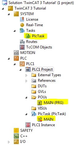
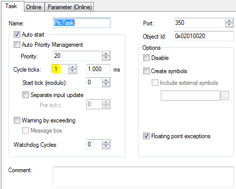
I’ve highlighted the important nodes, above. Under SYSTEM > Tasks, there is a new Task called PlcTask. A Task is what gets scheduled to run on the TwinCAT 3 runtime (that is, you can’t run a Program directly, you have to create a Task, and the Task then runs your Program). The Task has certain attributes, like how often to run. Double-click on the PlcTask node under the SYSTEM > Tasks node, and you’ll see this properties page for the Task:
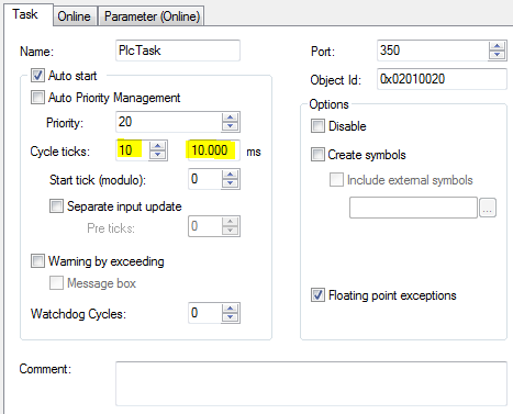
Note the two highlighted fields above next to the Cycle ticks field. By default the task is configured to run once every 10 cycle ticks, and that corresponds to once every 10 ms. That means the TwinCAT 3 runtime itself is actually configured to “wake up†once per millisecond, and every 10 times it wakes up, it executes this Task. You can then configure what this Task does when it runs. TwinCAT 3 has already done this by linking PlcTask to the MAIN program in PLC1. That means our program called MAIN in PLC1 will be executed once every 10 ms.
Configuring the Real-Time
All of the editing we’ve been doing in TwinCAT 3 XAE is a normal Windows program, and Windows is a general-purpose operating system, not a real-time operating system. The runtime component of TwinCAT 3 (called XAR) has to run under real-time conditions so that it won’t be pre-empted by other tasks on the computer while it’s busy executing machine control logic.
The TwinCAT 3 runtime pre-empts normal Windows programs by running in “ring 0” execution mode. In Windows there are only two execution modes: ring 0 and ring 3. Ring 0 is “kernel” mode, which is where all drivers and some internal windows code runs, and ring 3 is “user” mode, which is where normal windows programs run.
The runtime registers a timer interrupt to force execution of the runtime at a regular interval (called the clock tick). Interrupt routines run under ring 0, or kernel mode, so the runtime has access to the full resources of the computer. The runtime then executes Tasks, and each Task can do things like run PLC Programs, do Motion Control, interface with the EtherCAT I/O bus, or manage communications with the HMI. These interrupts pre-empt ring 3 (user-mode) programs so the runtime always gets priority over normal Windows programs, like the TwinCAT 3 editor or your HMI.
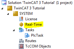
To configure the real-time behavior of TwinCAT 3, double-click on the SYSTEM > Real-Time node in the Solution Explorer (highlighted):
That will display the Real-Time configuration window:
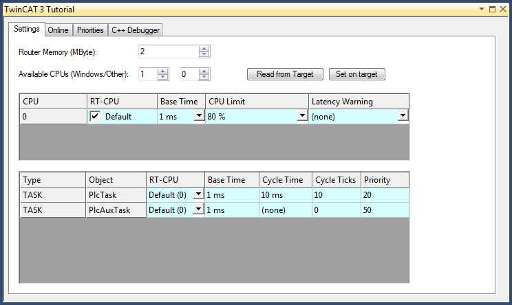
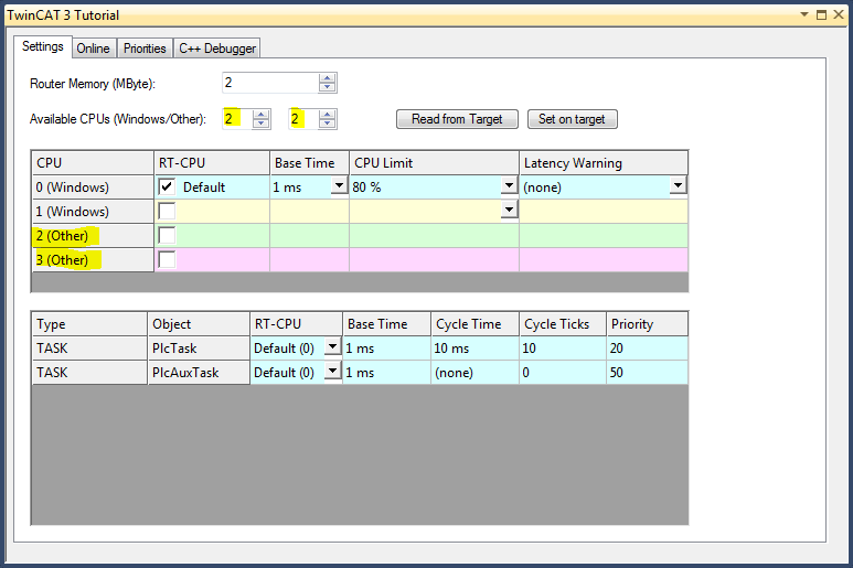
Notice that the “Available CPUs” shows only one CPU and it’s allocated to Windows. This is actually incorrect, because my computer is a Core i3 with 4 logical cores. Click the Read from Target button to make TwinCAT 3 read the actual configuration from the PC:
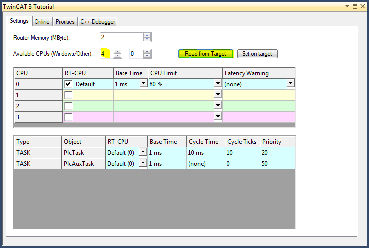
Now it correctly shows 4 cores. The cores are listed in the top list box, numbered 0, 1, 2, and 3. This configuration allows you to allocate cores between Windows, the TwinCAT 3 runtime, or both (or neither). I have found that mixing Windows and TwinCAT 3 on the same core might cause problems (at least in earlier versions of TwinCAT 3), so if you have a 4-core machine, I recommend allocating 2 cores for Windows and 2 cores for TwinCAT 3 runtimes. Changing this allocation requires a reboot, so save everything first.
Warning: only use the core isolation feature on Windows 10 if you have build 4020.0 or later. The “core isolation” feature is not compatible with Windows 10 in earlier versions. As far as I have been told, prior to build 4020.0, TwinCAT 3 won’t be able to see the cores set to “Other” and the only way to fix it is to use the “Reset this PC” feature of Windows 10.
If you have Windows 7, to change the core allocation, first click the Set on target button and the following window will pop up:
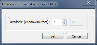
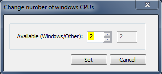
Here, we just set the number of cores available to Windows, and the remainder will be available to the TwinCAT 3 runtime. Change the number 4 to a 2, and then click the Set button:
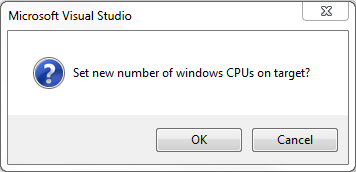
Click OK to the confirmation dialog box:
Then click OK to the Reboot question (save and close everything except TwinCAT 3 first):
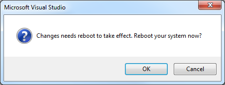
Hang on while the system reboots. Once it has rebooted, open the TwinCAT 3 solution again (either by double-clicking on the TwinCAT 3 Tutorial.sln file wherever you saved it, or by opening TwinCAT 3 XAE again and selecting it from the Recent Files list.
Now double-click on the SYSTEM > Real-Time node in the Solution Explorer again, and the real-time configuration window will look like this:
Notice that CPUs 0 and 1 still say “Windows” but cores 2 and 3 now say “Other”. Now we want to configure the TwinCAT 3 runtime to use cores 2 and 3. Under the RT-CPU column, check the checkboxes next to cores 2 and 3, and uncheck the checkbox next to core 0:
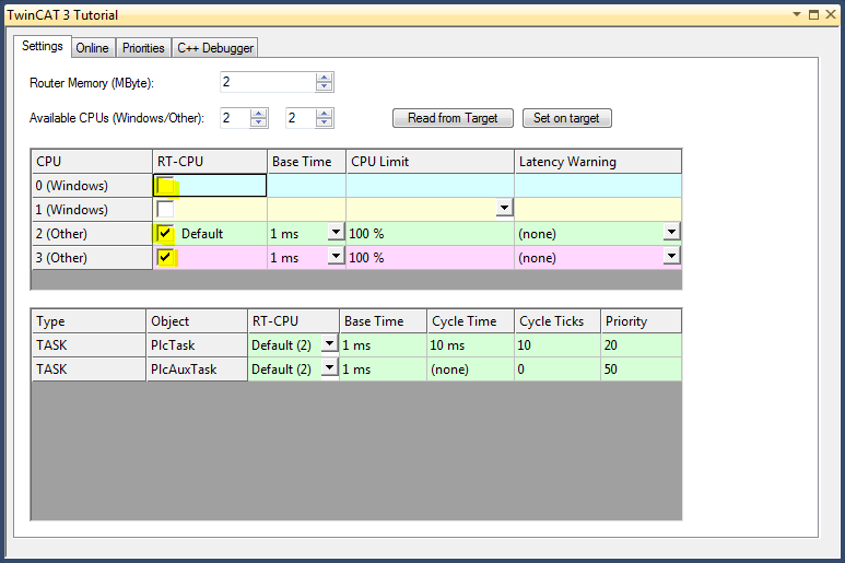
Notice that the CPU Limit column showed 80% next to core 0 when it was checked but shows 100% next to cores 2 and 3. That’s because when the TwinCAT 3 runtime has to share a core with Windows, we have to limit how much CPU time it can use, so that Windows still has some time to run user programs. However, when the runtime has a core all to itself, it can use to up 100% of the CPU time on that core.
The lower grid allows you to configure which tasks run on which core. Currently there are only 2 tasks: PlcTask and PlcAuxTask. The first is the task that was created when we created the PLC1 project. The second is an automatically created “housekeeping†task. For now, both are set to run on core 2, which is a bit wasteful of core 3, but in most real applications there’s a good chance of using two real-time cores. If your application has any motion control, it’s typical to run the motion control task on a separate core, and if you had more than one virtual PLC, you can choose to run them on different cores to balance the load.
Next, check the Base Time columns in the grids above. By default, the TwinCAT 3 runtime “wakes up” every 1 millisecond and checks if it needs to execute any Tasks. You can optionally change the Base Time in the upper grid. 1 millisecond is actually the slowest option. I find that 0.5 ms (500 us) works quite well for most PLC tasks. Note that this is much faster than you’ll be used to if you come from a more traditional PLC brand.
In the lower grid, you can see that even though PlcTask is running on core 2 with a 1 ms base time, it only runs once every 10 Cycle Ticks, so it effectively only runs once every 10 ms. I normally set this to 1 Cycle Tick so the PLC task would run every time the runtime wakes up. Note that your I/O refresh is tied to the speed of the Task using the I/O. That means if you set your PlcTask to run every 1 ms, then any I/O mapped to that Task also has to refresh once every 1 ms. The EtherCAT I/O bus is actually fast enough to do this even with a rather large number of devices on the bus.
To change the PlcTask so that it runs every 1 ms, double click on the SYSTEM > Tasks > PlcTask node in the Solution Explorer and change the Cycle ticks from 10 to 1:
Edit the PLC Logic
Add a Global Variable List
Let’s assume we’re going to program a grinding machine. Perhaps there’s a grinding wheel that needs to be turned on and off via a motor starter. Let’s start by declaring some variables for our PLC to interface with the outside world.
Under the PLC1 project, right click on the GVLs folder (highlighted):
From the context menu that appears, choose Add > Global Variable List…
A dialog box will appear where you can enter a name for your new Global Variable List. Let’s enter a suitable name for this list, like Grinder:
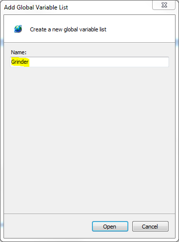
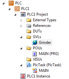
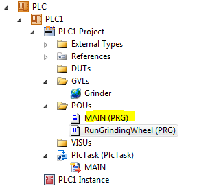
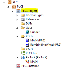
Then click the Open button. This will do 2 things: it will add a new Global Variable List in the GVLs folder, and it will open the new Grinders GVL for editing. Your PLC1 project will now look like this in the Solution Explorer:
…and the main editing area will now have a window open for editing the GVL:
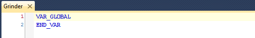
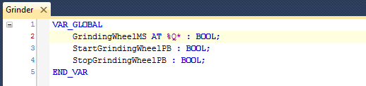
An empty Global Variable List isn’t very useful, so let’s add some variables. You’ll have to type the following exactly correctly between the VAR_GLOBAL and END_VAR lines:
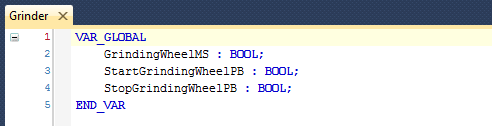
Note that I’ve created 3 variables, all of which are of type BOOL. The first variable (GrindingWheelMS) will represent the output for the motor starter that turns on the grinding wheel. The grinding wheel will run as long as this variable is on. The other two variables represent the inputs for start and stop pushbuttons (PBs) for the grinding wheel. We haven’t actually declared them as real outputs or inputs yet, but we’re going to come back to that later.
A BOOL value in TwinCAT 3 can take on two values: TRUE and FALSE. These variables can be used anywhere in the PLC program. It’s possible to create two Global Variable Lists that both have a variable of the same name. In that case, if you used that variable name in your program, when you tried to build your PLC project, the compiler will complain that the name is “ambiguousâ€. In that case you will have to prefix the variable name with the name of your Global Variable List. Due to this possibility, I always use the fully-qualified name (including the Global Variable List name) whenever I use a global variable in my logic, and I will do that in the rest of this tutorial. This is optional (and unnecessary) if you only have one GVL.
Adding a Ladder Logic Program
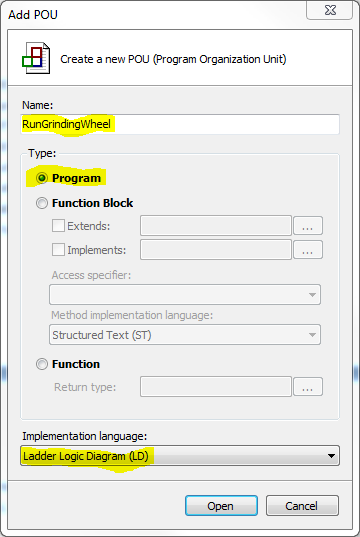
Now that we have some variables to control, let’s write some logic to control them. Right click on the POUs folder in the Solution Explorer and choose Add > POU…
In the Add POU dialog that pops up, enter a name for the new Program (RunGrindingWheel), choose Program under Type, and at the bottom under Implementation Language, choose Ladder Logic Diagram (LD):
Then click the Open button. Your new Program will show up under the POUs folder in the Solution Explorer, and the Program will be opened for editing in the main window:
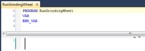
The editing screen is split into two parts. At the top is your list of variable declarations. These are similar to the variable declarations in a Global Variable List, but any variables declared here can only be used within this Program. It’s a useful place to declare variables for storing temporary values or helper coils. In order to write a simple start/stop rung, we won’t need to declare any local variables.
The bottom part of the screen is where you write the ladder logic. The numeral “1” indicates that it has already added a blank rung #1 for you. Let’s start by adding a coil to this rung. You can right click on the rung and choose Insert Coil from the context menu, or you can click the coil icon on the ladder logic toolbar at the top of the screen:
![]()
If you don’t see that toolbar, it might be hidden. Try right clicking on the blank toolbar spaces at the top of the screen and selecting the TwinCAT PLC FBD/LD/IL toolbar.
A third option is to click on the Toolbox vertical tab on the far left of the screen and drag and drop the coil icon from the toolbox over to the empty rung. Any of those options will result in a new coil being added to your empty rung:
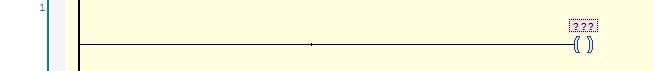
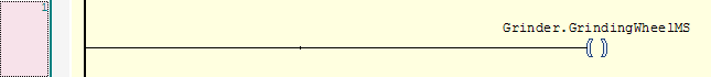
Notice that the coil has three question marks over it. This is where you have to enter the name of the variable you want to assign to this coil. Type the fully-qualified name of the grinding wheel motor starter variable into this field: Grinder.GrindingWheelMS:
Now let’s add the start button. The easiest way is to click on the rung right where the small tick-mark is in the center of the rung, and then right-click and choose Insert Contact from the context menu. Now you will see a contact inserted on the left of the rung:
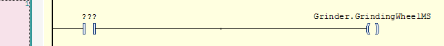
Then enter the fully-qualified variable name for the start pushbutton: Grinder.StartGrindingWheelPB:
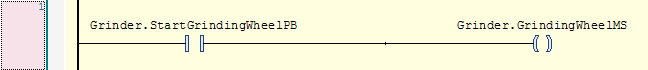
That will turn the motor starter on when the start pushbutton turns on, but of course it won’t stay on unless we add a seal-in circuit. To add a branch around the start button contact, select the contact, right click, and choose Insert Contact Parallel (below) from the context menu:
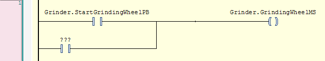
Edit the three question marks over the new parallel contact and change it to Grinder.GrindingWheelMS so that the coil seals itself in:
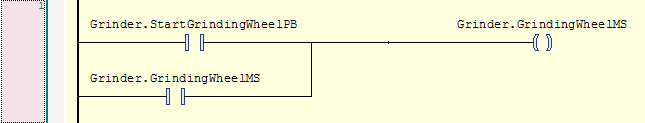
Now the motor starter will stay on after the start pushbutton input turns off, but it will keep running forever. Finally let’s add the stop pushbutton into the circuit as a normally closed contact. Select the section of rung between the branch on the left and the coil on the right (where the small tickmark is). Right click on this section of rung, and choose Insert Negated Contact from the context menu:
Finally, replace the three question marks above the normally closed contact with the fully-qualified variable name of the stop pushbutton: Grinder.StopGrindingWheelPB:
Finally, our start/stop circuit is complete! Remember to click the Save All button on the toolbar (it looks like a stack of three floppy disks).
Calling the Ladder Logic Program from MAIN
There’s one last thing we have to do before we can run our program. When the PlcTask runs, it will only execute the MAIN program, not our new RunGrindingWheel program. To get our program to execute every 1 ms, we need to “call” it from the MAIN program. Double click on the MAIN program in the POUs folder of the Solution Explorer:
That will open the program in the Structured Text editor:
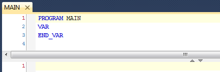
This looks very similar to the RunGrindingWheel program when we first opened it, but in this case, everything in the bottom is in Structured Text (ST) language instead of Ladder Diagram (LD). If you want, you can delete the MAIN program and replace it with a new MAIN program that uses Ladder Diagram. You have to remember to link the PlcTask to this new MAIN program because when you delete the old one it will lose the link.
However, since the MAIN program’s only job is to call other programs (in our example), it’s simple enough to do this in Structured Text. Change line 1 of the MAIN program to the following:
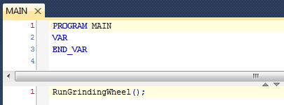
That is, it’s just the name of the program you want to call, following by an open and a closed bracket, and finally a semicolon. All statements in Structured Text end in a semi-colon. You could add other program calls below this one on new lines if you wanted. The program will call them once, in sequence, every time it runs (which is once every millisecond).
Downloading and Going Online
Build the PLC Project
It’s a good idea to “build” the PLC project before you try to download it. This will tell you if you have any syntax errors or misspelled variable names. In the Solution Explorer, right click on the PLC1 Project node and choose Build from the context menu:
This could take a minute while it compiles the PLC project. At the bottom of the screen, there’s a tab called Output, and it will show you the progress of the compiler:
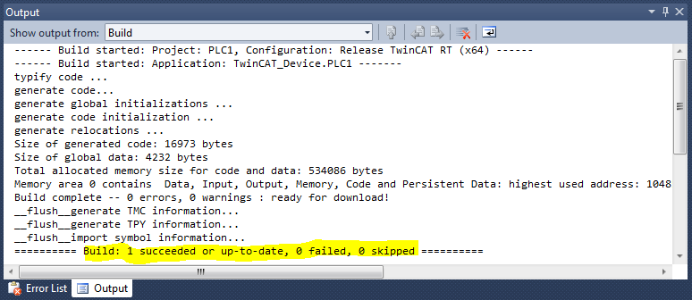
Take a look at the last line to see if there were any errors. You want it to say “1 succeeded” and “0 failed”. If it failed to build, you should look for error messages earlier in the output messages. Double-clicking on the error message should take you to the site of the error, or close to it.
Activate the Configuration
Now that our PLC project compiled successfully, the next step is to “activate the configuration”. What this does is:
- Stop the TwinCAT 3 runtime (all running programs will halt, and I/O will turn off)
- Apply the real-time configuration to the runtime (number of cores, tasks, etc.)
- Copy the compiled program(s) to the runtime
- Apply the “mapping” configuration (we will discuss mapping later)
- Restart the TwinCAT 3 runtime in run mode
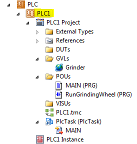
Note that when the runtime starts, it won’t automatically load the PLC program unless we “activate it as the boot project”, and it won’t start executing the PLC program unless we configure it to “autostart the boot project”. Do these two things by right clicking on the PLC1 node in the Solution Explorer:
…and then choose Activate Boot Project… from the context menu, and then do it again and choose Autostart Boot Project.
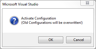
Now go to the top menu and choose TwinCAT > Activate Configuration from the menu. You will have to confirm this action with the following dialog box:
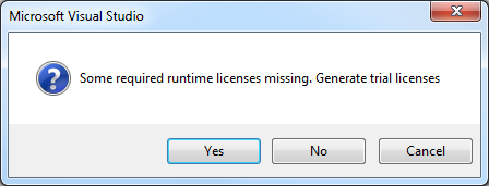
Click the OK button. Since we haven’t purchased a runtime license for this machine, it’s going to ask us if we want to generate “trial licenses”:
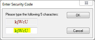
Click the Yes button. Then it will ask you to enter a captcha-type randomly generated group of characters to prevent you from automating the generation of trial licenses. Enter the letters in the text box underneath exactly as they appear (yours will be different than mine):
Then click the OK button. This generates a “trial” license which will expire after 7 days. Don’t worry too much about exceeding this 7-day limit though, as you can just generate another 7-day license when that happens. You will have to purchase an actual license only when you deploy to a production system.
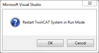
After generating the trial license, it will ask you if you want to restart in run mode:
Click the OK button. You should see the TwinCAT icon in the system tray (if it’s visible) turn from blue (config mode) to red (stopped) and then finally to green (running). If that happens, the TwinCAT 3 runtime is running in run mode on your PC!
If you look at the PLC1 node in the Solution Explorer window, you will also notice that it now displays a green rectangle, indicating that the PLC program is running:
Go Online
Like most other modern PLCs, TwinCAT 3 supports online debugging. To see this in action, start by double-clicking on the RunGrindingWheel program so that it’s open in the editor’s main window. Then select PLC > Login from the main menu:
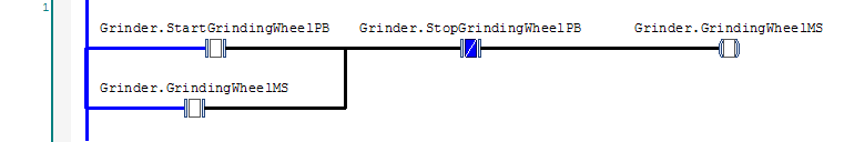
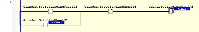
That puts the system into “online” mode and you can view the current state of the logic. Power is represented by the blue lines, and the status of the contacts and coils are represented by the blue rectangles in the middle of each. As you can see above, the Grinder.GrindingWheelMS coil is currently off, as are the start and stop pushbuttons.
Write Values to Variables (Online)
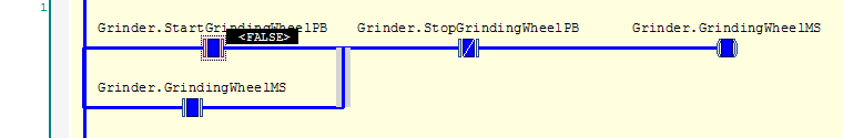
Even though the pushbuttons and motor starter variables aren’t connected to anything physical, the code is running. We can watch the state of the motor starter variable change by writing new values to the pushbutton variables. Let’s start by simulating someone pressing the start pushbutton. To do that, we’re going to write the value TRUE to Grinder.StartGrindingWheelPB. The first step is to queue a value to write. Hover your mouse over the center of the Grinder.StartGrindingWheelPB contact and double-click the small rectangle in the center:
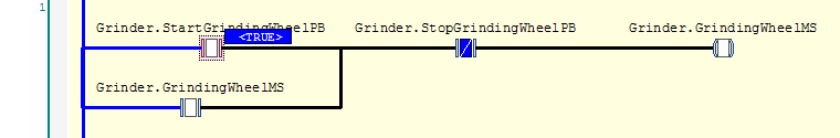
Next to the contact you can now see a queued write value (“TRUE“). You can change the queued write value to FALSE by double-clicking it again, and remove the queued write value entirely by double-clicking it a third time. When you’re ready to write the queued values to the PLC variables, choose PLC > Write values to all online applications from the drop-down menu at the top of the screen. You will immediately see the state of the rung change to reflect the new value:
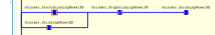
As you can see, simulating the start pushbutton turning on caused the logic to turn on the Grinder.GrindingWheelMS motor starter variable. Now let’s simulate releasing the start pushbutton by writing the value FALSE to the start pushbutton:
…and write the values by choosing PLC > Write values to all online applications from the drop-down menu at the top of the screen:
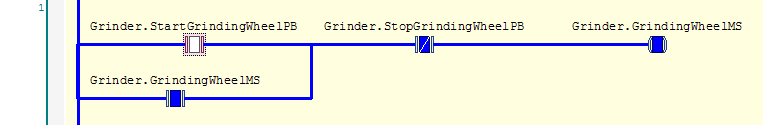
You can see that the motor starter variable (coil) stayed on. To finish the example, let’s simulate someone pressing the stop pushbutton by writing the value TRUE to the Grinder.StopGrindingWheelPB contact:
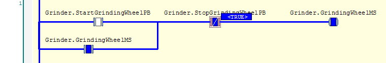
Writing the value then turns off the motor starter coil:
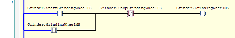
Writing a value to a variable is a one-time operation, so if you tried to write the value TRUE to the motor starter coil, it won’t appear to have any effect, because 1 millisecond later, the program logic will execute and change the value back to FALSE. If you want to override the logic, you need to use the “force.”
Force Variables (Online)
Forcing a variable is similar to writing a variable, except that the force overrides the logic of the program. For instance, we can force the motor starter coil to TRUE even though the logic is trying to keep it turned off. Start by double-clicking on the small rectangle in the middle of the motor starter coil:
You can see that we’ve queued the value TRUE, just like if we were going to do a variable write. However, in this case we’re going to choose PLC > Force values to all online applications from the menu at the top of the screen:
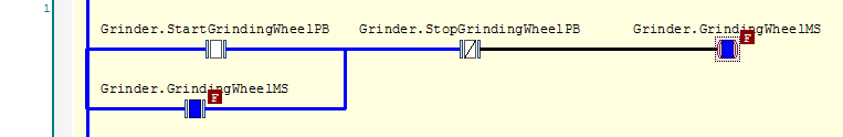
Forced variables are indicated with a small “F” in a red box next to the contact or coil that is forced. These variables will stay forced until you choose PLC > Unforce all values on all online applications from the menu at the top of the screen. You will also be asked if you want to unforce existing forces if you logout (go offline).
Using the TwinCAT PLC Toolbar
We’ve been going through the PLC menu at the top of the screen for all of the online functions, but there is also a toolbar that can give you quick access to these functions. It looks like this:
![]()
If you don’t see it, try right right-clicking on the toolbar area near the top of the screen and making sure that the TwinCAT PLC option is checked. If it’s already checked and you can’t see it, then you might have too many toolbars on one line, and that would force it to shrink the toolbar to almost nothing, like this:
![]()
If that’s the case, drag and drop the shrunk toolbar onto a new empty toolbar line and it will expand fully for you.
Making Online Changes to PLC Programs
TwinCAT 3 supports online changes to PLC program logic and variables.
TwinCAT 3 does not support online changes to the mapping between your PLC program and your physical I/O, so if you want to add or remove I/O, or you want to change the mapping between your PLC I/O and your physical I/O, you have to use TwinCAT > Activate Configuration from the top menu, and you will then have to restart the runtime, which will restart your PLC programs. This will cause your machine to stop.
The process for making an online change to a PLC program is:
- Make sure you are offline (logged out).
- Edit your PLC program logic and variables.
- Login (at the prompt, select Login with online change).
- If you’ve edited a variable (for instance, changed the type), it will warn you that the variable will be moved to a new memory location, and ask if you want to continue. This is safe to do unless you have an external program (like an HMI or a data collection system) reading or write variables in the PLC, in which case you may want to shut them down before continuing.
- Click Yes when it asks if you want to “update the boot project” (if you say No then your changes will be lost if you restart the runtime or reboot the computer).
Your changes will be applied without stopping the PLC program, and without any interruption to the machine.
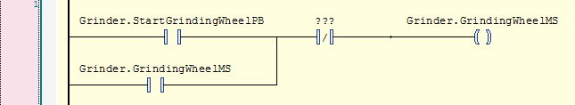
Now let’s make a change to our logic. Stop buttons on machines are sometimes wired using a normally closed contact instead of a normally open contact (so the input is on when nobody is pushing the button and the input turns off when someone pushes it). The reason for this is so that the machine will stop if the wiring to the stop button is disconnected (and it also allows you to chain stop buttons in series). Let’s change our grinding wheel start/stop logic to work with a normally closed stop pushbutton. First, make sure that you are offline. Choose PLC > Logout from the menu if you haven’t done so already. Here is the original logic:
Left-click to select the contact in the middle (Grinder.StopGrindingWheelPB):
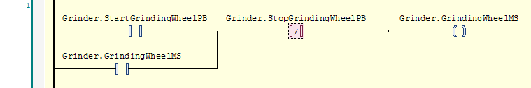
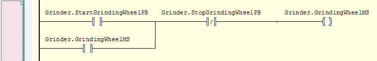
TwinCAT 3 has a handle shortcut for changing a normally closed contact to a normally open contact, or vice-versa: just press the slash key (“/”). Now your logic will look like this:
Login to the PLC by choosing PLC > Login from the menu. TwinCAT 3 will notice that the logic has changed and will ask you what you want to do:
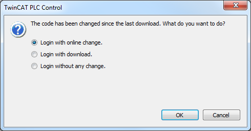
Leave Login with online change selected and click OK. Next it will ask you if you want to update the boot project:
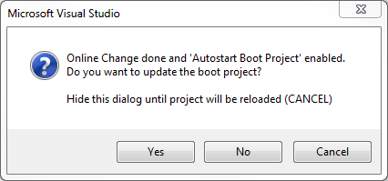
Click Yes. After that you will be online with the PLC, and your changes will be applied:
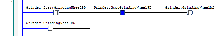
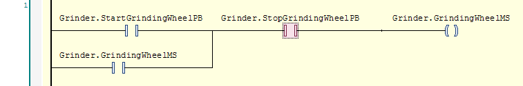
Notice that the Grinder.StopGrindingWheelPB contact is now a normally open contact, meaning the input has to turn off to stop the grinding wheel.
Designating PLC Inputs and Outputs
When we built our example PLC program above, we didn’t actually define which variables were inputs and which were outputs, so as far as the runtime was concerned, all of the variables were internal variables and the PLC didn’t interact with any physical I/O.
Designating a variable as an input or output only makes it available for mapping to a physical input or output during the mapping phase (after we’ve configured our I/O devices, which will be covered later).
We designate a variable as an input or output by modifying the variable declaration. Here is the original list of variables in the Grinder Global Variable List:
First let’s designate the GrindingWheelMS variable as an output. Change the variable declaration to the following:
As you can see, I’ve added AT %Q* directly after the variable name. The Q means output. You can designate the other two variables as inputs like this:
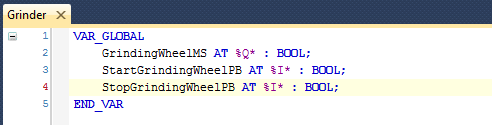
This is the same, but I’ve replaced the Q with an I meaning “input.” I know this is a weird syntax, but it’s a throwback to processors where you could (or had to) explicitly map variables to an input or output memory area. In this case, the asterisk means “I don’t care where you put it, just put it in the input or output map accordingly.”
Now you have to “build” the PLC project to see these variables show up on the PLC’s input or output map. Right-click on the PLC1 Project node in the Solution Explorer and choose Build from the context menu:
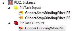
After the project is compiled, you will now see two new nodes under the PLC1 Instance node:
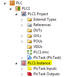
Expand the inputs and outputs by clicking on the small triangle next to each node:
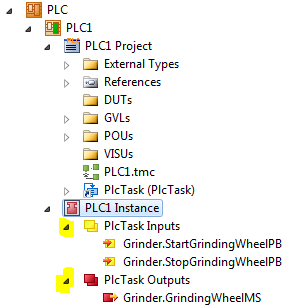
Now you can see the variables that you designated as inputs and outputs are available here for mapping. Normally you will map these variables to physical I/O, but they can also be mapped to I/O in the motion control task, the Safety program, or even to I/O from another PLC. That’s how you would be able to interlock two PLC programs together virtually without running any physical wiring. The runtime takes care of copying the data between each task, or between tasks and physical I/O.
Beware that if you change the name or type of a variable that has been designated as an input or output, TwinCAT 3 will unmap that variable from any existing mappings, and will only give you a rather easy-to-miss message in the output window when the PLC project builds. When you activate the configuration and restart, you may be left wondering why your output won’t turn on, or why your start button isn’t working. Note that when you’ve mapped a variable, the icon will change to include a small arrow, so you can tell which ones are mapped:
(All I did here was map the PLC output Grinder.GrindingWheelMS back to PLC input Grinder.StartGrindingWheelPB, which is a rather silly thing to do in real life.)
Whew! That concludes the Quickstart chapter of this tutorial! You’ve now covered all the basics of downloading, installing, configuring, programming, going online, forcing, and making online changes to your PLC program in TwinCAT 3. That’s a lot of new information, but I hope it gives you a good enough introduction to feel like you can experiment and play around with the system some more. When you’re ready, you can move forward in the tutorial with more advanced topics.
This chapter is part of the TwinCAT 3 Tutorial. Continue to the next chapter: Structuring PLC Data.