This chapter is part of the TwinCAT 3 Tutorial.
In TwinCAT 3, the ladder logic editor shares a lot of functionality with the function block diagram editor. In some ways, the function block editor is just the ladder logic editor without contacts and coils. All of the function blocks available in the function block diagram editor are also available in the ladder logic editor, so I consider the ladder logic language to be a super-set of the function block diagram language.
Ladder logic, however, requires the concept of a “rung”, which is just power (represented as a BOOL signal) entering from the left, and connecting all of the language elements together within the rung (a.k.a “network” in TwinCAT 3).
The EN Input and ENO Output
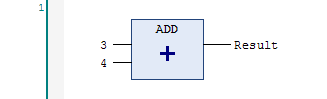
Here is what the ADD function looks like in the function block diagram editor:

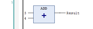
Here is what it looks like in the ladder logic editor:
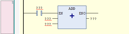
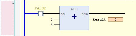
Notice that the editor added the EN input and the ENO output automatically. The EN input is an enable input. The instruction is only executed if the EN input is true. Here is a disabled ADD instruction (the EN input is FALSE), and you can see that the ADD instruction isn’t being executed because the Result is still 0:
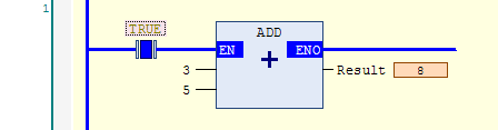
While the EN input is true, the instruction executes:
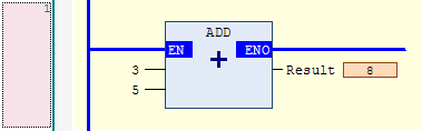
Please note that the contact before the ADD instruction is generally unnecessary if you want it to execute all the time:
The ENO output is for continuing the rung to the right, so you can chain multiple instructions together like this:
However, once you start using longer variable names, doing this can cause rungs that are very wide and don’t wrap very nicely, so as a matter of ladder logic programming style, a rung like this should generally be split into two rungs:
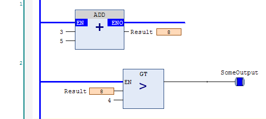
While the novice programmer often assumes that a program with fewer rungs is better, the only thing that should guide your choice is readability. One good rule of thumb is that any instruction that modifies a variable should be the end of a rung. Ladder logic programmers implicitly assume that inputs are on the left and outputs are on the right. In the example above, the ADD instruction modifies the Result variable, so we should stop the rung there and continue the logic in a new rung.
The Rung as RValue and LValue
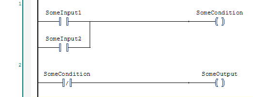
Take a look at this typical rung made up of only contacts and coils:
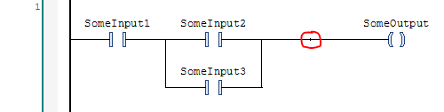
I highlighted a vertical line with a red circle around it. The vertical line separates two parts of the rung: the RValue and LValue. These names are actually confusing because the RValue is everything to the left of the vertical line, and the LValue is everything to the right of it. Why is this backwards? In a traditional programming language like C, consider a statement like this:
int a = 5 + 3;
Everything on the left of the equals sign is the LValue and everything on the right is the RValue. The LValue is the part being modified (the result of the assignment) and the RValue is the expression being evaluated. It’s just that in ladder logic, this is reversed. The assigned variable (the coil) is on the right and the expression (the inputs) are on the left.
What does this mean in practice? Basically it means that everything on the left of the vertical line will be evaluated first, and then everything on the right will be assigned. Only coils can go on the right, and coils can’t go on the left.
That might seem a bit restrictive if you’re coming from Allen-Bradley, where you can put a coil instruction anywhere you like. In practice, this is only a minor adjustment to your thinking.
Automatic Conversion Between Function Block Diagram and Ladder Logic
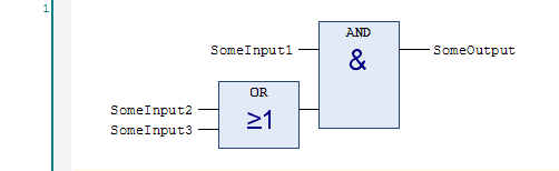
One interesting feature of TwinCAT 3 is that it can convert between function block diagram and ladder logic. If you copy the rung above and paste it into the function block diagram editor, you get this:
Interestingly, if you take this ADD instruction in function block diagram:
…and then you paste it into the ladder logic editor, you’ll get this:
Why didn’t it include an EN input and an ENO output when it converted it to ladder logic? As I said, the ladder logic language in TwinCAT 3 is a super-set of the function block diagram language. The ladder logic editor can support any valid function block diagram construction.
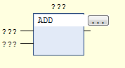
If you right click on a rung and choose Insert ADD Box from the context menu, you’ll get an ADD instruction with the EN input and ENO output. However, if you right click (typically on an empty rung) and select Insert Empty Box from the context menu, you’ll get a box without the EN input and ENO output. Then you can just type the name of the function you want at the top of the box:
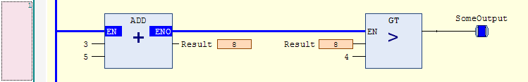
However, this presents a problem. The ladder logic editor won’t allow you to connect the output of the ADD instruction to a variable. You can insert another empty box and use a GT (greater than) instruction to compare it, which gives you a BOOL output, which you can then connect to a coil. What you should be able to do is right click and choose Insert Assignment, but this option isn’t enabled in the ladder logic editor. I actually believe this is a bug in the editor, and that it might be fixed in a future version. In the mean time, you can actually build your network in the function block diagram editor, copy it, and paste it into the ladder editor, and it will compile and run just fine.
Blocks with Variable Numbers of Inputs
Some blocks allow you to add extra inputs. For example, an ADD function can have 3 or more inputs:
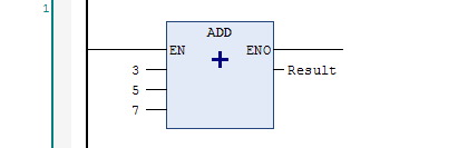
To add an input, right click on the block and select Append Input from the context menu.
Contacts and Coils
Let’s take a look at the ladder logic specific instructions in more detail.
The Coil
Here is the coil instruction:
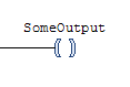
The coil instruction does one thing: it assigns the result of the RValue expression (the result of the logic on the left) to the coil variable.
In other PLCs, the coil instruction does a second thing: during program startup (sometimes referred to as the pre-scan), it sets the variable to FALSE. This is an important property of coils in ladder logic: they are expected to default to off after a program start.
In TwinCAT 3, persistence is controlled by whether or not you declare a variable as a persistent variable. In real life, coils turn off when they lose power, so an experienced ladder logic programmer (or an electrician) looking at a rung like this:
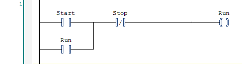
…will expect the Run coil to drop out if the program restarts (particularly due to the machine being turned off and back on again). If you make the Run variable persistent, then you will break this expectation. There is a principle of programming called The Principle of Least Astonishment. Don’t make a coil variable persistent because it breaks this principle. Use a Set/Reset instruction pair instead (explained later).
Similarly, as a matter of programming style, do not use the same variable in two different coil instructions. The editor and compiler will allow you to do this, but it’s considered bad ladder logic style. If you find that you have logic that requires you to do this, consider writing that logic in structured text language instead. Ladder logic should mimic physical relays whenever possible, and using the same variable in two coil instructions breaks this mental equivalency.
The Negated Coil
If you have a regular coil and you select it and press the slash key (“/”), it will change it into a Negated Coil:
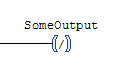
This is an example of an instruction that was probably included because it was easy to add, but should never have been included in the language. It’s easy to explain what this does: during program execution, if the rung input condition is TRUE, it sets the variable to FALSE, and if the input condition is FALSE then it sets the variable to TRUE. The problem is that there’s no real-world counterpart to a negated coil.
Logically this:
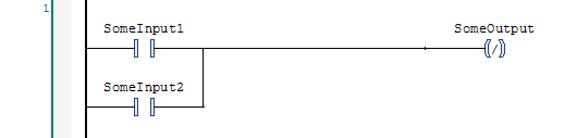
…is equivalent to this:
The latter two-rung logic is the preferred form. Please avoid use of the negated coil instruction. One of the purposes of ladder logic is to allow electricians to debug it. The negated coil is not intuitive to an electrician and even an experienced ladder logic programmer will frown when they see it.
Set and Reset
While a coil should revert to “off” when the program is restarted, it’s sometimes preferable to remember the state of a variable through a program restart. This is the purpose of Set and Reset instructions:
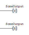
In the physical world, we would use a latching relay. The latching relay has two inputs called Set and Reset (or Latch and Unlatch). Energizing the Set input will move an internal solenoid to change the relay to the “on” position. A spring mechanism will hold it in this position, so it will remember its state even after power is removed. Likewise, energizing the Reset input will move the solenoid the other way, to the “off” position.
Note that in TwinCAT 3, to get the variable to retain its state, you will have to make it a persistent variable. The important thing to note is that when a ladder logic programmer sees a pair of Set/Reset instructions, they will expect this to be a persistent variable, so please don’t break this expectation.
Normally Open and Closed Contacts
The Normally Open Contact:
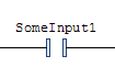
…sets the rung output condition to the logical “and” of the rung input condition and the state of the contact’s variable. In the physical world, a normally open contact is a switch that only allows power to pass if the coil variable is in the “on” state. The normal state of a coil is off (de-energized) which means a normally open contact is normally “open” (i.e. not conducting).
The Normally Closed Contact:
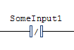
…sets the rung output condition to the logical “and” of the rung input condition and the negated state of the contact’s variable. In the physical world, a normally closed contact is a switch that only allows power to pass if the coil variable is in the “off” state.
The TwinCAT 3 ladder logic editor has a handy shortcut: to toggle a contact between normally open and normally closed, but select it and press the slash (“/”) key.
Positive and Negative Transitions
TwinCAT 3 supports Positive and Negative Transition contacts:
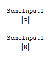
What these instructions do is generate a one-scan pulse on a positive or negative transition of the given variable, and then “and” the pulse with the rung input condition. In other PLCs this type of instruction is sometimes referred to as a “differentiate up/down”, “rising/falling edge”, or a “one-shot rising/falling” instruction. It’s important to note that these TwinCAT 3 instructions generate pulses based on the transitions of the variable (SomeInput1 in this example) and not based on the rung input condition. (There are built-in function blocks called R_TRIG and F_TRIG that will look for transitions on their inputs.)
Internally, the Positive and Negative transition contacts operate by implicitly storing a copy of the variable and comparing the current value against the value from the last scan to determine if a transition occurred.
It’s worth noting that the internal variable copy seems to be initialized to FALSE on a program start. This means that if you use a Positive transition contact with a variable that is already TRUE when the program starts, the instruction will generate a pulse on the first program scan. This may be unexpected.
For instance, if you have a persistent variable, and used a Positive transition instruction on it, and it was TRUE when the program shut down and restarted, most programmers wouldn’t expect the Positive transition instruction to generate a pulse when the program started. Unfortunately you need to be aware of this and program accordingly. If it’s important, you can use the built-in R_TRIG function block and make the function block instance itself persistent. This will save the state of the internal memory variable through the program shutdown and restart.
For some added fun, the Negative transition instruction doesn’t behave this way because the internal state is initialized to FALSE so when it’s used on a variable that’s already FALSE on a program restart, the instruction doesn’t see a transition. (Ultimately I think this is a bug, and that the Positive transition instruction’s internal variable should have been initialized to TRUE to avoid this inconsistent and surprising behavior. It’s possible that Beckhoff may “fix” it in the future, but they might be hesitant because it could constitute a breaking change in a few programs.)
Using Function Blocks in Ladder Logic
In TwinCAT 3, a function block has inputs, outputs, and internal state. The obvious example is a timer or a counter. TwinCAT 3 has two timer instructions: a delay-on timer (TON) and a delay-off timer (TOF). Here’s an example of a TON instruction:
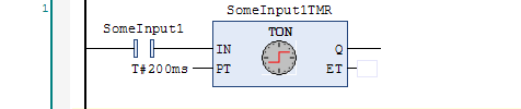
What this does is create a variable (SomeInput1TMR.Q) where the on is delayed by 200 ms. The timer will still turn off immediately when SomeInput1 turns off. On the other hand, a TOF instruction turns on immediately when the input turns on, but delays turning off:
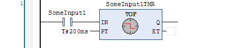
A delay-on timer is more common, but a delay-off timer is typically used when you have a fast pulse (like a quick button-push or brief sensor) and you want to elongate that into a longer, more consistent pulse width.
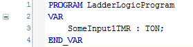
What differentiates a function block from a function is that a function block can store state internally. In the case of a timer, the obvious internal state is the Elapsed Time (ET) output. Since function blocks store internal state, TwinCAT 3 needs somewhere to put it, so you have to declare a variable. The variable is entered above the function block:
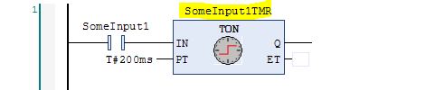
You have to declare this function block variable just like any other variable in your program:
I find that most function blocks are declared in the program variables, not in global variables, though there are some exceptions. Where you declare them is up to you and the needs of your application.
In addition to timers, you can also declare counters. Here is a count-up counter (CTU):
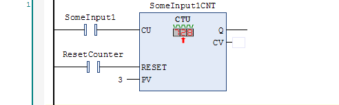
The count-up timer will start at zero (the CV output means current value) and will add one to the current value on each rising edge of the count-up (CU) input. The counter will turn on the Q output if the CV value is greater than or equal to the PV value. However, please note that the counter will continue counting even after the Q output is on. This is different than counters in some other PLCs. Turning on the RESET input causes the CV output to change to zero and the counter won’t respond to the CU input. Note that if you set PV to zero, the counter still functions but the Q output will always be on.
The opposite of the count-up timer is the count-down timer (CTD):
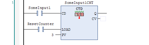
As you can see, instead of a RESET input, the count-down timer has a LOAD input. When the LOAD input turns on, it sets the current value (CV) output to the value of the preset (PV) input. Each rising edge on the count-down (CD) input will decrement one from the CV output value. The counter will count down to zero, but won’t continue counting below zero (it can’t because the CV output is an unsigned variable). The Q output will turn on if the CV output is zero.
Note that both the CTU and CTD counters are 16-bit counters (WORD variable), so their max values are 65535. You can, of course, write your own counter function blocks if you need one that can count higher.
Note that TwinCAT 3 also offers the up/down counter (CTUD) which is a combination of the CTU and CTD counters:
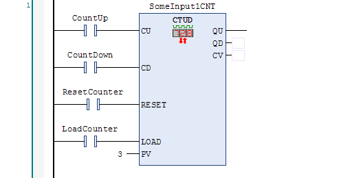
As you can see, you can RESET the counter (to zero), LOAD the counter (to the preset value) and count it up or down. The counter is “reset dominant” meaning if both the RESET and LOAD inputs are on at the same time, the RESET input takes priority. Like the count-up counter, it can happily count above the preset value, but like the count-down counter it can’t count down below zero. The QU output turns on if CV is greater than or equal to PV, and the QD output turns on if CV equals zero.
The Many Faces of the MOVE Function
The simple MOVE function:
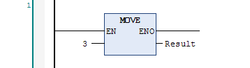
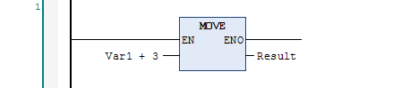
It copies the value on the left to the variable on the right. The input on the left can be any expression:
Here’s a useful case where you have an angle in degrees and you want to take the COS of it, which expects an angle in radians:
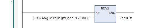
…which is equivalent to this:
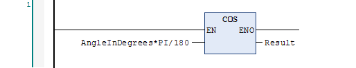
The latter is probably more readable since COS is what you’re “doing” and the expression in the input is just a conversion. Here’s another typical use of the MOVE function to do unit conversions:
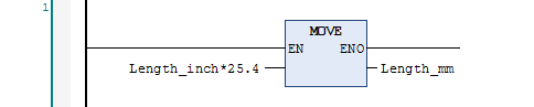
Note that a purist would say that the value 25.4 needs to be declared in a constant, like INCH_TO_MM. Personally, for well-known conversions, I find that using the value 25.4 is simple and readable. Obviously you shouldn’t be using 3.14 for the value of PI because (a) it’s wrong(er) than than value available in the built-in constant and (b) the constant is shorter and more readable.
If you really don’t want to use a constant, consider creating a function, like in_to_mm(). This is both readable, short, and precise.
It’s also a very good idea to put the unit name in your variable name, such as Length_mm or Length_inch. In the United States and many facilities in Canada the operators will still want to see distances shown in inches, but Beckhoff motion control and servo products all use mm exclusively, so this type of conversion is commonplace. Putting the units in the variable name will help you keep track and make errors more obvious.
Variable Type Conversions
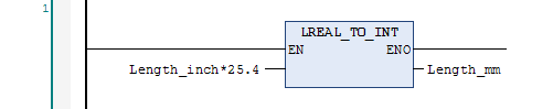
TwinCAT 3 has a full suite of built-in unit conversion functions. Some conversions can be done implicitly, like converting from an integer value to a floating point value, but you will still get a compiler warning. To get rid of the warning, or to do a conversion from floating point to integer, use an explicit conversion, like this:
Summary
The ladder logic editor in TwinCAT 3 is a powerful super-set of the function block diagram editor. It allows you to mix standard contacts and coils with the entire library of built-in function blocks, plus any new functions or function blocks you write.
Remember to always focus on writing readable logic. In particular, make sure you’re writing logic that an electrician can read, follow, and understand. The ability for an electrician to understand ladder logic is one of the main reasons that we write in ladder logic to begin with. Always keep that in mind.
This chapter is part of the TwinCAT 3 Tutorial. Continue to the next chapter: Writing your own Functions and Function Blocks.