Never will you see a more important Ladder Logic Programming Pattern that is simultaneously so often abused. The Set/Reset pattern, also known as the Latch/Unlatch pattern or simply “Latch Bit” is for remembering some on/off state of the machine that has to survive a power outage:
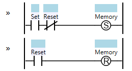
Set/Reset
Note that in an Allen-Bradley PLC, you will see the terms Latch (L) and Unlatch (U) used instead of Set and Reset.
In the logic shown above, this is a “reset dominant” Set/Reset. That’s because if both the Set and Reset conditions are active at the same time, the Memory will be reset. Of course you can make this “set dominant” by simply reversing the logic:
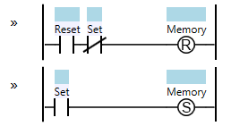
Set/Reset – Set Dominant
Before you can really understand this pattern, you need to understand a little about where ladder logic came from. Before the invention of the PLC (and for many years after) machine logic was programmed with actual physical relays. The reason that a normal “coil” in a PLC (e.g. as seen in the Start/Stop Circuit pattern) will revert to a de-energized state (off) when the PLC loses power is that it’s meant to mimic the behavior of a relay. If you shut off the main power switch to a machine, all of the relay coils will lose power so they’ll all revert to a de-energized state.
Of course, even in those days you sometimes wanted the machine to “remember” some condition even if the power to the machine was lost. For this purpose you could buy a special device called a two-coil Latching Relay. This relay had two coils in it: a Set coil and a Reset coil. When you energized the Set coil it shifted an internal mechanism to the “on” position, but this position was mechanically maintained with spring force. Energizing the Reset coil would shift the internal mechanism to the “off” position. If neither coil were energized, the relay would stay in its last position, hence why it was called a “latching relay”.
When PLCs were invented, they wanted to mimic this two-coil relay logic, which is why they split the Set/Reset feature into two coils: “S” and “R” (or “L” and “U”). It’s up to the ladder logic programmer to use these responsibly, but unfortunately many programmers don’t. Unfortunately nothing stops you from having multiple Set coils for the same Memory bit sprinkled all over your logic. This makes the logic much more difficult to understand and troubleshoot. Use of the Set or Reset coils on the same memory bit more than once is considered an anti-pattern. I strongly urge you to structure your ladder logic to use one of the forms shown above, so that you have exactly one Set coil and exactly one Reset coil for each Memory bit. Not only that, please put them on adjacent rungs.
When I wrote my own ladder editor, I strongly believed that the language should prevent novices from making this mistake, so it only has a combined Set/Reset instruction:
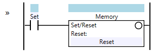
Set/Reset – SoapBox Snap
The language simply won’t allow you to have two Set or two Reset coils for the same Memory bit.
The Set/Reset pattern is often used for part tracking in a machine. Imagine you have a machine where a robot places a part into a fixture, and then some manufacturing operation is performed to that part (like a grinding or milling operation), and then another robot removes the part from the fixture, moving it to the next station. Ideally there will be a sensor in the fixture to indicate if a part is present. You will need some way to “remember” the status of the manufacturing operation performed on that part. First you will need a Set/Reset to remember that the manufacturing operation has been started, and secondly you will need another Set/Reset to remember that the manufacturing operation has been completed. In the event of a power outage, the machine can then recover: if neither memory is on, then you still need to perform the manufacturing operation on the part, and if both are on then you just need to remove the part from the fixture. If the Started memory is on but the Finished memory is off, then you may need to scrap the part, or you may be able to continue the operation.
Extra credit: PLCs were meant to mimic relay logic. However, digital logic (in the form of microchips and transistors) has the concept of a digital latch, also called a “flip-flop” or a “set/reset latch”. It’s important to note that a digital circuit like this will not retain its state in the event of a power outage. Interestingly, the Allen-Bradley line of PLCs uses battery-backed SRAM (which is really just a massive array of flip-flops) to store the program state. When the PLC loses power, the internal battery is what keeps latches latched. Note that this battery doesn’t last forever, and if you let an Allen-Bradley PLC sit unpowered for a long time, it will lose its memory. Other PLCs rely on writing their internal state to a “persistent storage” medium, like built-in flash memory or a hard drive, and they’re designed to have enough power remaining in their capacitors to allow this persistence to take place when power is lost.
More Patterns of Ladder Logic Programming.
I’ve been using or understanding the terms Latching and Sealed in interchangeably for about 6 months now until reading this article. Thanks for clearing that up for me. I see now how unsafe it can be to use latching instructions for motor control.
Thanks for this post.it is really explanatory.
Thanks again for these ladder logic programming tools.
I am reading / working through the book by Petruzella and it is very nice to have something IRL-ish available by which to practice the examples, questions, and problems therein.
For the (S/R) instruction in the Soapbox SNAP Arduino Toolkit, I am finding is not persistent between resets / power cycles.
Am I missing something or was the (S/R) instruction not implemented making use of free EEPROM Data space or free Flash Program Memory? / Does the 3-4 orders of magnitude in write time for Flash – EEPROM versus a machine instruction cycle simply kill this notion in terms of performance / scan cycle times?
@LLWJ – correct, the “Soft” SoapBox Snap runtime that runs on the PC directly should preserve the state of Set/Reset instruction coils through a restart, but that feature is unfortunately not implemented in the Arduino runtime.
At this point, my suggestion, if you need to survive a power outage, is to run it on a UPS.
@SW
Thanks for confirming the (S/R) behavior on the SNAP Arduino implementation. For my demonstration purposes, I went with a “logical” approach whereby the first rung is a sealed in coil labeled pwrOn. I then simply prefix all the
pwrON
following rungs with a –| |– contact, like so:
Of which the (S/R) state survives a cycling of pwrON while the Sealed In Coil reverts to not being energized.
thanks again
I am a serial offender on this one, I guess. I use (S) and (R) probably more than I should.
My primary “transgression” is that I will keep a Set and Reset pair on adjacentor nearly adjacent rungs, but then add a rung full of duplicated (R)s near the bottom for certain bail-out states/conditions.
With a ladder editor that showed gridlines and had plenty of columns visible, Inused to also be very religious about putting (S) coils in one column and (R) coils in another. This made it easy to visually search to make sure every (S) had an (R).
Thanks for offering these tips. I will try to make use of these recommendations.