Category Archives: Home Automation

Whole Home Energy Monitoring with the Brultech ECM-1240

This Christmas I asked Santa for a Brultech ECM-1240 whole home energy monitoring system, specifically the DUO-100 package. After reviewing various products, I really liked that this one was priced quite reasonably for the hardware, and that they published the communication protocol.

You (or a licensed electrian) install the ECM-1240 at your main electrical panel. Each ECM-1240 has 7 channels. In my case, the first channel on the first unit measures the incoming main line current. For the other 13 channels you are free to choose various circuits from your panel that you want to monitor. You can gang various circuits together into a single channel if you like (all lighting loads, for example). The device uses current transformers on each circuit for the monitoring. These are installed inside the panel. The hot wire coming out of each breaker has to go through a current transformer, so this isn’t a simple plug-in installation; there is wiring to be done.

The company distributes software for the device for free, or you can choose from various 3rd party software. Alternatively you can configure the device to send data to websites.

I’m not a fan of sending my home energy data to someone else’s server. Apart from being a huge privacy concern (it’s pretty easy to see when you’re home, and when you went to bed), I don’t want to pay a monthly fee, and I don’t want to worry about how to get my data from their server if they go out of business or decide to discontinue their product. For those reasons, I installed their software. It’s basically a flash website that I hosted on our Windows Home Server, which is conveniently the computer hooked up to the ECM-1240’s as well.

At first their software worked quite well, but over time it started to show problems. After just less than 2 months of logging, the flash program was so sluggish to load a page that it took over 2 minutes to refresh a screen. Admittedly I was running it on an older PC. Additionally, in that amount of time it had already logged about 680 MB of data. That seemed excessive. It also logged to a SQL Lite database (a single-user file-based database), and unfortunately kept the database file locked all the time. The website would end up locking the database and packets started getting buffered in the logging software until you closed down the website and released the lock.

I decided I’d just write my own software:

Power Cruncher Viewer

I’m a C# developer, so that was my language of choice. If you’re a .NET developer too, I’ll include a link to my source code at the end of this post. Note that this software isn’t commercial quality. It’s semi-configurable (channel names, and so on) but it assumes you have a 14 channel system where the first channel is the main panel input. If your system is different, you’ll have to make some modifications.

These devices I purchased use a serial port for communication, but they give you an RS232 splitter cable so you only have to use up one serial port on your PC. Their software relies on putting the device into an automatic send mode… the device itself chooses when to send packets. If the load changes significantly on one of the circuits, it triggers an immediate packet send. Unfortunately with 2 devices on the same RS232 port, you can sometimes get a collision. Their software deals with this by detecting it and ignoring the data, but I had a sneaking suspicion that once in a rare while, it ended up getting a corrupt packet, and there was at least one point where their software logged an extremely high energy reading, and it didn’t make any sense. Therefore I wrote my software to use a polling mode. It requests data from the first device, waits about 5 seconds, requests it from the other device, waits 5 seconds, and repeats. On average we get one reading about every 10 seconds from each device. Testing seemed to indicate this was about as fast as I could go because there was a reset period after you talked to one device where you had to wait for it to time out before you could address the other one. In retrospect, if you just hooked them up to 2 separate serial ports you could probably poll the data faster.

Next I had to choose how to log the data. I really wanted the data format to be compact, but I still wanted decently small time periods for each “time slice”. I also didn’t want to be locking the file constantly, so I just wanted to be able to write the data for each time slice, and be done with it. I settled on a binary format with fixed length records. Here’s how it works: each day’s data is stored in a separate file, so the data for April 1st is stored in a file called 2015-04-01.dat. The device generates values in watt-seconds. I calculated that at a maximum current of 200A (100A panel x 2 legs) x 120V, then in a 10 second time slice I should log a maximum of 240,000 watt-seconds. A 20-bit number (2.5 bytes) can store a maximum value of 1,048,575. I didn’t want to go smaller than half-byte increments. So, 14 channels at 2.5 bytes per channel gave me 35 bytes for each 10 second time slice, and since the devices generate voltage I figured I’d log the voltage as a 36’s byte just to make it an even number. Using those numbers, running 24 hours a day for 365 days a year, this will use up under 110 MB/year. Not bad. A flat binary file like this is also fast for data access. The data is small, and seeking a time slice can be done in O(1) time. After you find the first time slice you just keep reading bytes sequentially until you get to the end of the file or your last time slice. Hopefully no more 2 minute load times.

I broke up my application into multiple programs. The first is a utility program called Uploader.exe. This is a command line program that reads the data from a device and just spits it out to the screen. Useful for testing if it works.

The second is called Logger.exe and it does just that. It uses Uploader.exe to read values from the two ECM-1240 units at 5 second offsets and writes the data to XML files into a PacketLog folder. Each file has the timestamp of when it was read, and the device number to indicate which device it came from.

The third program is called PacketProcessor.exe. This program monitors the PacketLog folder and waits until it has at least one packet from each device after the end of the current time slice it’s trying to build. If it does, it calculates the values for the current time slice and appends it to the end of the current day’s data file. It then deletes any unnecessary packets from the PacketLog folder (it keeps at most one packet from each device before the end of the most recently written time slice).

To host Logger.exe and PacketProcessor.exe, I used nssm a.k.a. “the Non-Sucking Service Manager”. It’s a small command line program you can use to run another command line program as a service. Very handy.

The fourth program is called Viewer.exe. It’s the graphical interface for viewing the power data. Here’s a screenshot of data from one day (just the main panel power, click on it to make it bigger):

Main Panel Power over one day

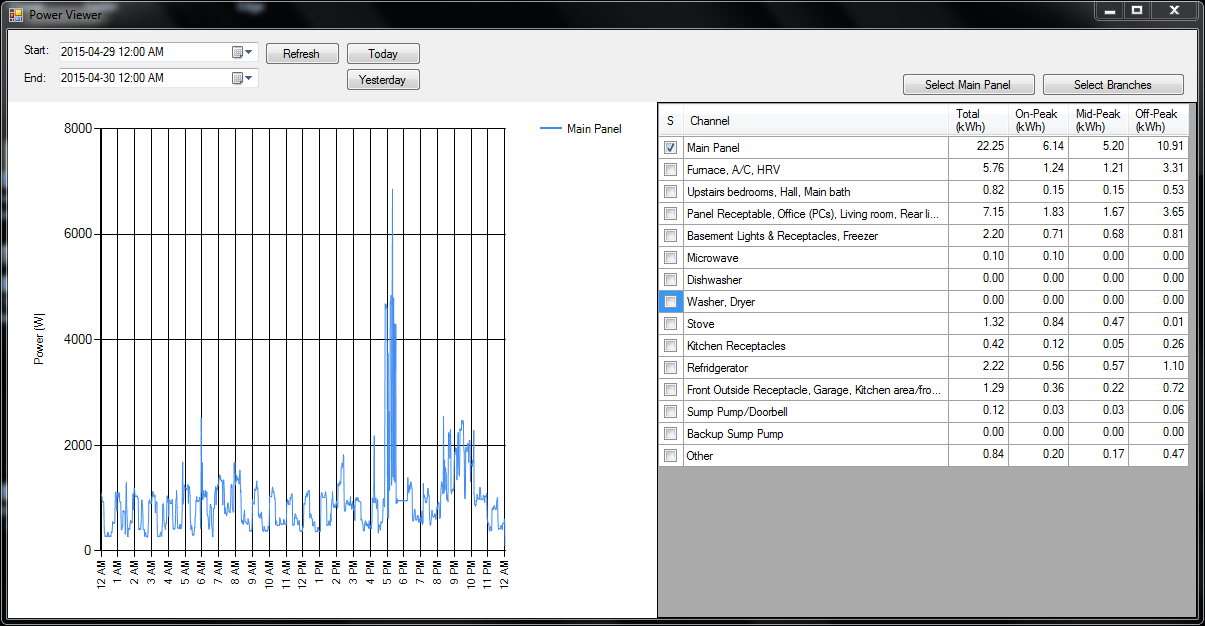
That’s a rather typical day. The big spike around 5 pm is the oven, and you can see the typical TV-watching time is after 8 pm once the kids are in bed. On the right you can see it breaks out the power usage in kWh for each channel, and in our area we have time-of-use billing, and this actually breaks the power usage out into off-peak, mid-peak, and on-peak amounts.

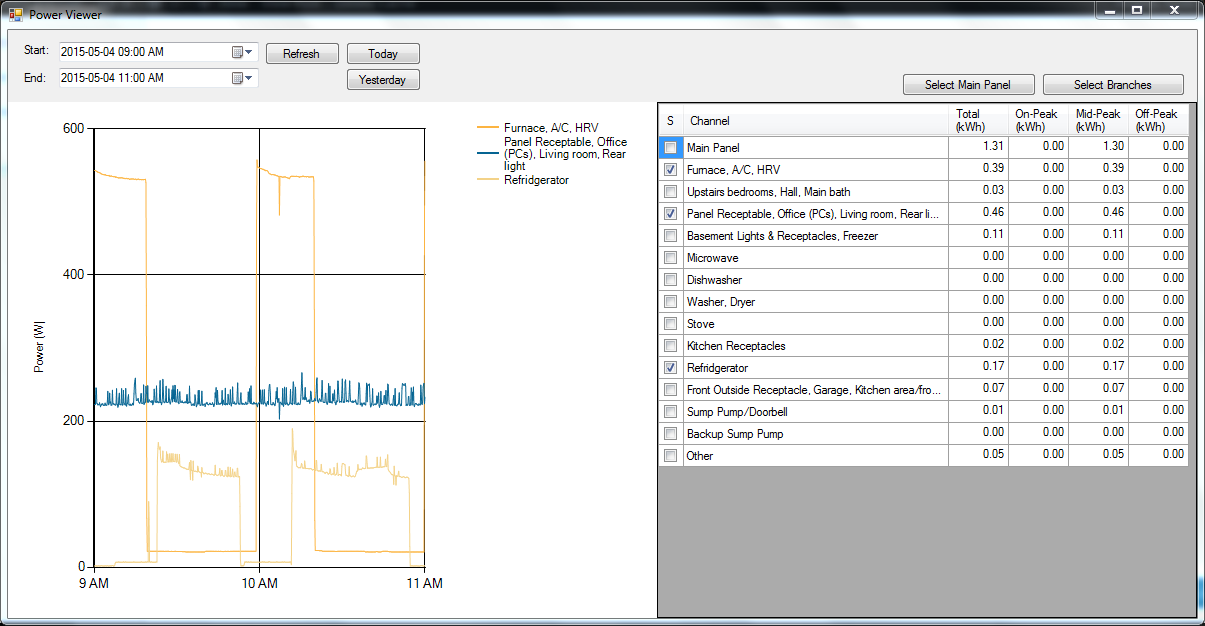
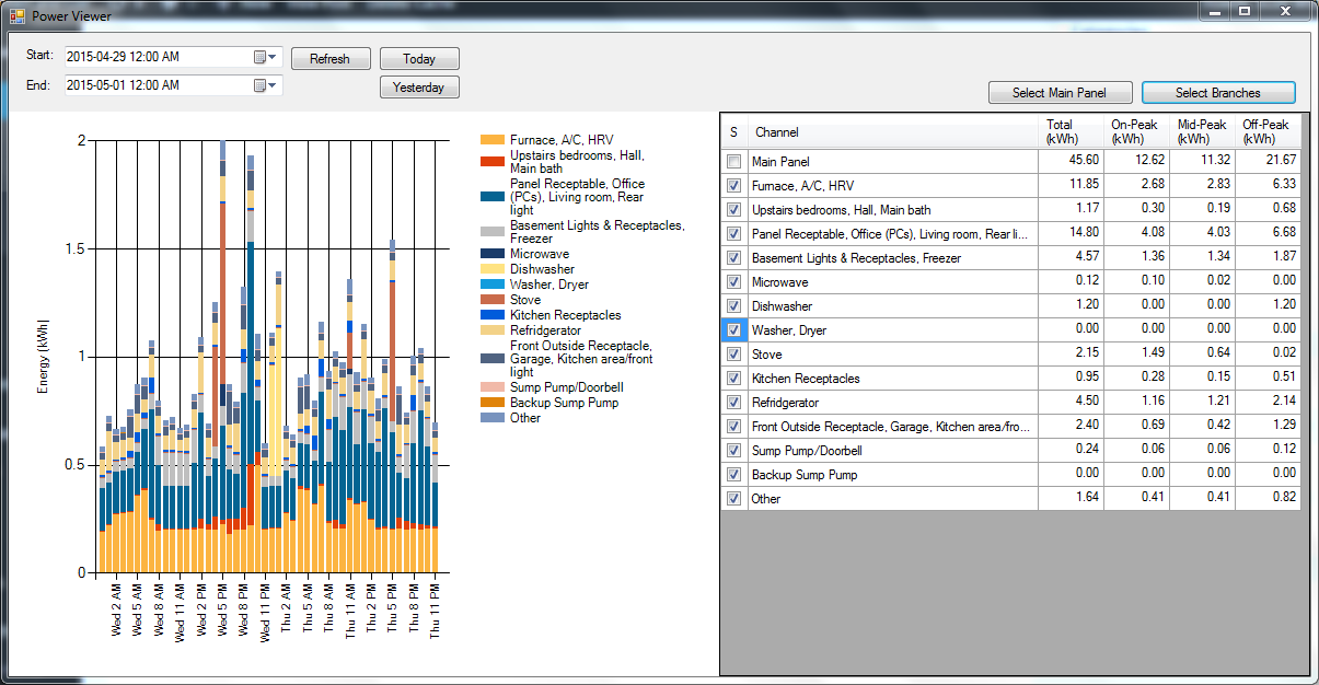
The viewer program uses a line graph for all time periods under 24 hours, but switches to an hourly bar graph for periods longer than that. Here is a 48-hour time period, and I’ve changed from just the Main Panel to all the branch circuit channels instead:

Branch circuit power over 48 hours

If you ask for a time period of more than a week it switches into daily bars:

Branch circuit power by day

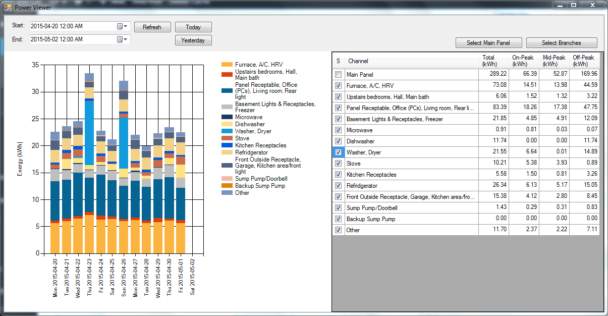
Pulling up two weeks of data like that was actually very fast, just a few seconds.

One final feature I added was email alerts. One of the channels monitors just my backup sump pump circuit. If it ever turns on, that’s because my main sump pump has failed, and I want to know. Through a configuration file, I configured an alarm to email me if that circuit ever records more than 5W of power in a 10 second time slice. I did a little test and it works (it does require that you have a Gmail account though).

Here’s the source code, if you’re interested:

As always, feel free to email me if you have questions or comments.

As Technology Buffs, We’re Blinded to the Obvious Uses of Technology

Are you old enough to remember the early 90’s? Almost nobody was “online” then. It’s hard to believe how much the internet has changed modern life since then. I just went through my bookshelf and got rid of all the reference books (which I could have done years ago) because the internet makes them obsolete.

Do you remember having to look up some arcane technical detail in a book? Do you remember how painful that was? Do you remember connecting to a BBS using a phone line and a 2400 baud modem? I do.

Back then when we tried to imagine the future, we (as geeks) really got it wrong, and surprisingly so. We were the ones who were supposed to see the possibilities, yet we consistently imagined the things we wanted to do with the technology instead of the things the average person wants to do with it. You see, geeks aren’t average people, so we’re sometimes blind to the obvious.

As geeks, we imagined having our own robot to do our bidding, or some kind of virtual reality headset for driving cars around on Mars. In reality, the killer app for the masses was the ability to take a picture of something, write a short note about it, and send it to all your “friends”. The funny thing is, if you asked a geek in the early 90’s if that feature could be the basis of a company valued in the billions of dollars, they’d have laughed you out of the room. The idea just wasn’t that revolutionary. After all, we’d had fax machines for several years, and email/usenet were already out there. Geeks already had access to this technology, and thought nothing of it.

Average people, if they even saw this technology, didn’t see what was under their noses either, simply because it wasn’t sexy yet. Let me be clear, when I say “sexy” I mean it literally. The average young person isn’t like a geek. They don’t have robots and virtual reality sets on their mind, they want to know who’s going to be at the party on Saturday, who said what about who, and if so and so is available. Modern social media succeeds because it helps people satisfy the most basic of “normal” wants.

Where am I going with this? When you look at the bleeding edge of technological progress today it’s easy to spot the trends. Open source hardware has really taken off, specifically 3D printing and other “home” fabrication technologies. We’re also seeing an explosion of sensors, not just in your phone, but also plugged into consumer devices, with most of them uploading their data to central servers (e.g. the popular Nest Home Thermostat).

We all want to know what the next big thing will be, and we’re hopelessly bad at predicting it, but we still like to play the game. If we want to know where this new hardware renaissance is leading, we need to look at the space where these new technologies intersect the wants of average people. Only about 1% of users are the kind that participate by actually creating new content, so I definitely don’t see a future where everyone is designing new things in Google Sketchup and printing them out on their 3D printer they bought at Wal-mart. The thing about 3D printers is that they print things we can buy much more cheaply (little plastic trinkets), especially if it’s the type of thing that a lot of people want, so there’s an economy of scale to support manufacturing it.

There is something that everybody wants to create at home, and can’t be mass produced in a factory on the other side of the world: freshly prepared food. Gourmet food, even. People pay big bucks for fancy coffee makers that make fancy coffee from packets with barcodes containing individualized brewing instructions. It’s not a big stretch to imagine a machine that can whip up fancy cocktails, or dozens of fancy hors d’oeuvres for a party, or even print out your kids’ drawings on their Christmas cookies with icing from a 3D printer. Maybe a gizmo that carves an apple into the shape of their favorite cartoon character? (Of course, you know these will be re-purposed to make snacks for bachelorette parties, right?)

That’s the easy stuff. Honestly, Eggs Benedict seems like it’s well within the range of possibilities, and who wouldn’t want to wake up on Sunday to the sizzle of eggs and bacon, along with the usual coffee brewing?

Of course, if we automate the food preparation and we’re collecting all this data with sensors, it won’t be long until we’re automating the control of our caloric intake.

That’s my guess anyway: all this new technology’s going to end up in your kitchen. Which is cool with me (that doesn’t mean I can’t still have my 3D printer…)

More Control Systems Found Attached to the Internet

Back in November I published a blog post about Finding Internet-Connected Industrial Automation Devices and one of the scariest things I found was a wind turbine in Oklahoma with no apparent authentication.

Recently Dan Tentler took this several steps further and posted his video from the LayerOne 2012 security conference, where he shows you a vast array of non-secure devices connected to the internet, much of which can interact physically with the real world, including control systems. Here’s his extremely fascinating video, and it’s worth watching all 45 minutes (note that he also has a screenshot of the Endurance Wind Turbine interface that I found in my original post):

OWI-535 Robot Arm with USB Controller from C# and .NET

I got the OWI-535 “Robot Arm Edge” 5-Axis robot arm and USB Controller add-on for Christmas:


The robot arm comes as a kit that you assemble yourself, and my 3 year old and I had lots of fun putting it together (it helped to have some tiny fingers around, honestly). It comes with a manual controller that allows you to rotate all 4 joints, plus the gripper. It’s fun to play around with, but let’s be honest, everyone wants to hook it up to their computer.

Unfortunately the software that comes with the USB controller works on Windows 7, but “32-bit only”. That was a little annoying, but hey, I didn’t really want to stick with their canned software anyway. I figured I would see if I could get it to work from C#. I was surprised to find a great site by Dr. Andrew Davison in Thailand who wrote some Java code as part of his site for his book Killer Game Programming in Java (chapter NUI-6 Controlling a Robot Arm, which doesn’t appear in the book). Surprisingly he went as far as to do the inverse kinematic equations so you can give the arm a set of X,Y,Z co-ordinates (in mm) in “world frame” and it will calculate all the join angles to get to that location, and then used timed moves to get the arm into that position.

His Java library uses libusb-win32, and that library has a .NET equivalent called LibUsbDotNet. The API’s don’t appear to be the same, but thankfully I managed to find a thread on SourceForge about controlling the OWI-535 using LibUsbDotNet. So, over the course of a couple of nights, after the kids went to bed, I ported Dr. Davison’s Java code over to C# (quite easy actually) and replaced the libusb-win32 calls with LibUsbDotNet API calls. It worked!

Here is the .NET solution that I wrote called TestOwi535. I used Visual C# 2010 Express Edition to write it, so that’s free. Also, you must download and install LibUsbDotNet first and run the USB InfWizard first to generate a .inf file (you have to do this with the robot arm plugged in and turned on), and then use that .inf file to install LibUsbDotNet as the driver (technically you’re installing libusb-win32 as the driver and LibUsbDotNet is just the C# wrapper).

If you right click on the C# project in the solution explorer, you’ll find 3 options for startup object: MainClass is the original code I found in the SourceForge thread, but it’s just proof of concept code and only moves one joint in one direction for a second. The ArmCommunicator class is an interactive console application that allows you to move all joints (and control the gripper and light) by typing in keyboard commands. Finally the RobotArm class is the full inverse kinematics thing. In the last case, make sure you start with the arm at the zero position (base pointing away from the battery compartment, and all joints in-line straight up in the air, gripper pointing directly up, and gripper open). It will do a move to the table, to the front right of the arm, close the gripper, and then move back to zero and open the gripper.

Unfortunately that’s where you start to see the obvious deficiency of the arm: it has no position feedback. That means even though it tracks its position in the code, the physical position eventually drifts away from the internal position tracking, and the arm eventually doesn’t know where it is (it’s just using timed moves). One of the biggest areas where you could improve it is to change the joint rates so that it knows that the joints move faster when going down than when going up.

Still, it’s a neat little toy for the price. I’m going to start hunting around for a way to add joint position feedback, as that would really improve the performance. I also want to rewrite a new module from the ground up that allows concurrent joint moves (this one only moves one joint at a time). Ideally you want to control this thing in “gripper frame” instead of “world frame”.

Happy hacking!

Outdoor G-Scale Garden Railroad: Detecting the Trains

A little while ago I told you about an ongoing project to automate my parents’ G-Scale outdoor model railroad. Today I’m going to add a bit more detail about the solution: specifically, how do you sense the location of the trains?

Layout

The layout is broken into 3 lines: a “Figure 8” line, a “Point-to-Point” line, and a “Main Line”, which has various track switches, sidings, etc. The interesting thing about the Figure 8 and Point-to-Point lines is that they cross, and one of the goals is to prevent trains from colliding.

Some other goals include:

  • The point-to-point should start at one station, move to the other station, stopping out of site for a while. It should stop at each end-station for an adjustable period of time, and return.
  • The Point-to-Point and Figure 8 lines have uphill and downhill sections, so the speed needs to be varied in these sections.
  • The Figure 8 line has two programmable stops, but the train shouldn’t necessarily stop at both stops every time.
  • We want to run multiple trains on the main line. Some will be stopped on a siding while others are running, and then they will switch.
  • All tracks need the ability to be manually operated.

The Figure 8 Line from behind "Stan's Speed Shop"

Power

All existing locomotives in the system use “track power” (DC voltage applied across the two rails of the track). The voltage applied to the track is applied to the motors in the locomotives, and this controls the speed.

There are some advantages to this: it allows you to run “stock” (unmodified) engines, and it’s compatible if someone wants to bring over a “guest” engine (either a track powered or battery powered model). It’s also compatible with “DCC” controlled locomotives which, as I understand it, are backwards compatible with track powered systems.

Control?

Whether you use a PLC or a PC for control, being able to control the voltage to a track (to control a motor speed) is pretty much a solved problem, so let’s assume we can do that for now. The main problem is location sensing. In order to tell the locomotives to stop, wait, start, etc., you need to know where they are.

Your first thought, as a controls engineer, is some kind of proximity sensor. Unfortunately there are some significant problems with this:

  • Metal-sensing proxes are expensive, and the locomotives are mostly plastic. We’re trying to avoid retrofitting all locomotives here. You might be able to sense the wheels.
  • Photo-sensitive (infrared) detectors, either retro-reflective or thru-beam type, are popular on indoor layouts, but they apparently don’t work well outdoors because sunlight floods them with infrared.
  • Reed switches are popular, but you need to fit all your engines with magnets, and they are a bit flaky. Magnets and reed switches actually work well if you have the magnet on the track, and the reed switch mounted to the engine, in order to trigger whistles, etc., but even then they’re not 100% reliable, in our experience.
  • All proximity detection strategies require you to run two wires to every sensor, which is a lot of extra wiring. Remember, there are lots of little critters running around these layouts, and they tend to gnaw on wires. Fewer wires is better.
  • Having sensors out in the layout itself means you’re exposing electrical equipment to an outdoor environment. At least you can take the locomotives in at night, but the sensors have to live out there year-long. I’m a bit concerned by that thought.

Solution: Block Occupancy Detection

The solution we found was a technique called “block occupancy detection.” This is a fairly common method of detection in some layouts. A couple of years ago, I built a simple controller that solved the crossing detection problem between the Figure 8 and Point-to-Point lines using block detection to know where the trains were. It worked great, so we decided to use it for the entire system.

Here’s how it works: you divide up your track layout into “blocks”. Blocks can be any size, but they are typically anywhere from about 4 feet long, up to the length of a train, or a bit more. One rail on the line is “common” and isn’t broken up. The other rail is the one you cut into electrically isolated sections.

So, the wire from the common side of your speed controller goes directly to the common rail, as it did before. However, you have to split the “hot” side of your speed controller into as many circuits as you have blocks. Each block is fed from a separate circuit, which means you have to run a “home run” wire from each block back to your power supply.

Then, the “block occupancy detection” circuit is wired in series with each block circuit (between the speed controller and the block). Here’s what one block detection circuit looks like:

This is an interesting circuit. On the left you can see a bridge rectifier, with the + and – terminals curiously shorted out. This is a hacked use of the device. All we really care about is that we want to create a voltage drop across the device when current is flowing through the wire to that block. One diode creates a voltage drop of 0.6 to 0.7 V, and the way we’ve wired it, whether the speed controller is in forward or reverse, the current always has to take a path through two forward-biased diodes. That means, when current is flowing to the block (i.e. there’s an engine in that block) then we get a voltage drop of 1.2 to 1.4 V across this device (or -1.2 to -1.4 V if it’s in reverse). A standard bridge rectifier is just a handy component to use because it’s readily available in high current ratings for a couple of dollars each.

We’re using that constant voltage to drive the input side of an LTV-824 opto-isolator chip. Notice that it’s a bi-directional opto-isolator, so it works in forward or reverse too. On the output side of the opto-isolator, we can run that directly into a PLC input (the input we’re working with here is sourcing and has a pull-up resistor built-in).

If you’re using a regular straight-DC analog controller, that’s all you need, but in this case we’re using a pulse-width-modulated (PWM) speed controller. That means the PLC input is actually pulsing on and off many times a second, and if you’re at a slow speed (low duty cycle), then the PLC may not pick up the signal during it’s I/O scan. For that reason, I found that sticking a 1 uF capacitor across the output will hold the PLC input voltage low long enough for it to be detected quite reliably. This, of course, depends on your pull-up resistor, so a little bigger capacitor might work better too.

Filtering in the PLC

This worked quite well, but needed a bit of filtering of the signal in the PLC. The input isn’t always on 100% while the locomotive is in the block, so once a block is latched as “occupied”, I use a 1-second timer of not seeing the input on before I decide that the block is clear.

I also have to see an adjacent block occupied before I clear a block. That solves the problem of “remembering” where an engine is when it stops on the track and there’s no longer any current flowing to that block.

Of course, this means you can end up with “ghosts” (occupied blocks that are no longer truly occupied because someone picked up a locomotive and physically moved it). I provided some “ghost-buster” screens where you can go in and manually clear occupied blocks in that case.

Pros and Cons

I like this solution for several reasons: all the electronics are at the control panel, not out in the field (except the wires to each block, and the track itself). Also, the components for one block detector are relatively inexpensive, and we’re working on a bit of a budget here (it is a hobby, after all). I think reliability and simplicity also fall into the Pro column. As long as you can get a locomotive to move on a segment of track (the track needs cleaning from time to time), then the PLC should be able to detect it. You don’t need to deal with dirty photo-detectors or extra sensor wires. The same wire that carries the current to the block carries the signal that the block is occupied.

On the other hand, there are some negatives. This system, as designed, has 21 different blocks, which means 21 home-run wires, buried in the ground, in addition to the commons (plus the track switch wires, but that’s a story for another post). Also on the negative side, you don’t get 100% accurate position sensing. Actually, you get pretty accurate sensing at the edges of the blocks (you’re pretty sure you know where the locomotive is the moment is crosses from one block to the next), but you’re not sure where it is in the middle of the block.

You do have to make other compromises in the track system. There are some accessories (like lighted end-stops) that draw power from the track. This current draw makes that particular block show up as occupied all the time. You either have to modify the accessory to use battery power, or you have to run extra wires to that accessory.

You also have to take the length of train into account. You know which blocks are occupied by current-drawing locomotives and cars (like lighted observation cars and caboose’s), but not every car draws power. Your design and control system needs to take into account whether or not your train will occupy more than one block at once, and whether the end of the train will be detected. This is most important when trying to run multiple trains on one track, where you want the back train to avoid running into the end of the first train.

Next

I hope that’s been educational. 🙂 I’m still not done programming the PLC, and I’m waiting for a component to arrive for the throttle controller right now. I’ll post more information over the next few weeks.

Sneak Peak: Outdoor Model Railroad Automation

Several years ago my parents decided they were going to build a Garden Railroad in their back yard. It’s been an ongoing hobby project since then, and it’s been growing substantially every year:

West Station on the Point to Point Line

This is “G Scale” (around 1:22.5 scale) outdoor model railroading. It’s really a combination of three things: model railroading, building miniatures, and gardening. This recent weekend was the local club’s open-house day, and I was invited along to see many of the layouts. Each layout kind of emphasizes its own focus: some are more focused on gardening, others on the miniatures, etc.

Anyone who does anything remotely related to computers knows that every relative you have thinks you know everything there is to know about computers, and you’re destined to spend the rest of your family holidays removing spyware and running ccleaner on their computers, not to mention reassuring them that it’s OK to reboot the computer to see if the problem goes away.

Being in industrial automation, though, you never get people asking you to automate something; it’s just a little bit too abstract for most people to grasp. However, when your parents get themselves a model train set, they may not know exactly what you do for a living, but they certainly know that if you can program conveyors, robots, and cranes, you should be able to figure out how to make their trains do what they want them to do. Automatically.

Of course, as a control systems guy, you can’t look at your parents’ 24V model train set and not think about how you’d hook up a PLC to it. Especially when they offer to finance the project.

I’m happy to report that we’re progressing well. The goal is to have it running in fully automatic mode before the end of the month. I’ll post some pictures, hopefully some videos, and some technical information about how it was accomplished. Stay tuned.

Insteon and X10 Home Automation from .NET

I’ve been playing with my new Smarthome 2413U PowerLinc Modem plus some Smarthome 2456S3 ApplianceLinc modules and two old X10 modules I had sitting around.

Insteon is a vast improvement over the X10 technology for home automation. X10 always had problems with messages getting “lost”, and it was really slow, sometimes taking up to a second for the light to actually turn on. Insteon really seems to live up to its name; the signals seem to get there immediately (to a human, anyway). Insteon also offers “dual-band” technology, meaning the signals are sent both over the electrical wiring of the house, and over a wireless network. On top of this, Insteon implements “mesh networking”, acknowledgements, and retries. The mesh networking means that even if two devices can’t directly communicate, if an intermediate device can see both, it will relay the signal.

Now, where Insteon seems to have improved leaps and bounds on the hardware, the software support is abysmal. That’s not because there’s anything wrong with the API, but because they’ve put the Software Development Kit (SDK) behind a hefty license fee, not to mention a rather evil license agreement. Basically it would preclude you from using any of their examples or source code in an open source project. Plus, they only offer support if you’ve purchased their SDK.

So, I’ve decided to offer free technical support to anyone using a 2413U for non-commercial purposes. If you want help with this thing, by all means, email me, post comments at the end of this post, whatever. I’ll be glad to help you.

Let’s start by linking to all the useful information about Insteon that they haven’t completely wiped off the internet (yet):

Now how did I find all this information? Google. SmartHome (the Insteon people) don’t seem to provide links to any of this information from their home or (non-walled) support pages, but they either let Google crawl them, or other companies or organizations have posted them on their sites (I first found the modem developer’s guide on Aartech’s site, for instance). Once you get one document, they tend to make references to the titles of other documents, so you could start to Google for the other ones by title. Basically, it was a pain, but that’s how it was done.

Now, whether you buy the 2413S (serial) or 2413U (USB), they’re both using the 2412S internally, which is an RS232 device. The 2413U just includes an FTDI USB-to-Serial converter, and you can get the drivers for this for free (you want the VCP driver). It just ends up making the 2413U look like another COM port on your PC (in my case, COM4).

So, assuming you know how to open a serial port from .NET, and you got done reading all that documentation, you’d realize that if you wanted to turn on a light (say you had a switched lamp module at Insteon address “AA.BB.CC”), you’d want to send it this sequence of bytes (where 0x means hex):

  • 0x02 – start of message to PLM
  • 0x62 – send Insteon message over the network
  • 0xAA – high byte of Insteon ID
  • 0xBB – middle byte
  • 0xCC – low byte of Insteon ID
  • 0x0F – Flags (meaning: direct message, max hops)
  • 0x12 – Command byte 1 – means “turn on lighting device”
  • 0xFF – Command byte 2 – intensity level – full on

… after which the 2413U should respond with:

0x02, 0x62, 0xAA, 0xBB, 0xCC, 0x0F, 0x12, 0xFF, 0x06

… which is essentially just echoing back what it received, and adding a 0x06, which means “acknowledge”.

At that point, the 2413U has started transmitting the message over the Insteon network, so now you have to wait for the device itself to reply (if it does… someone might have unplugged it, after all). If you do get a response, it will look like this:

  • 0x02 – start of message from 2413U
  • 0x50 – means received Insteon message
  • 0xAA – high byte of peer Insteon ID
  • 0xBB – middle byte
  • 0xCC – low byte of peer Insteon ID
  • 0x?? – high byte of your 2413U Insteon ID
  • 0x?? – middle byte of your 2413U Insteon ID
  • 0x?? – low byte of your 2413U Insteon ID
  • 0x20 – Flags – means Direct Message Acknowledgement
  • 0x12 – Command 1 echo’d back
  • 0xFF – Command 2 echo’d back

If you get all that back, you have one successful transaction. Your light show now be on! Whew, that’s a lot of overhead though, and that’s just the code to turn on a light! There are dozens of other commands you can send and receive. I didn’t want to be bit-twiddling for hours on end, so I created a little helper library called FluentDwelling so now you can write code like this:

var plm = new Plm("COM4"); // manages the 2413U
DeviceBase device;
if(plm.TryConnectToDevice("AA.BB.CC", out device))
{
    // The library will return an instance of a 
    // SwitchedLightingControl because it connects 
    // to it and asks it what it is
    var light = device as SwitchedLightingControl;
    light.TurnOn();
}

I think that’s a little simpler. FluentDwelling is free to download, open-sourced under the GPLv3, and includes a full unit test suite.

It also supports the older X10 protocol, in case you have some of those lying around:

plm.Network.X10
    .House("A")
    .Unit(2)
    .Command(X10Command.On);

There are quite a few Insteon-compatible devices out there. In addition to lighting controls, there is a Sprinkler Controller, Discrete I/O Modules, a Rain Sensor, and even a Pool and Spa Controller. That’s just getting started!

Finally Getting an Arduino

I cruised through January in a kind of sleep deprived stupor (we just had our second child this December). Things are finally swinging back to normal, and I’m getting my geek back on.

I’ve been looking for a less expensive way to do discrete (or analog) I/O over WiFi for homebrew projects. I want something that can be compatible with SoapBox Snap (the open source ladder logic editor/runtime I’ve been working on), so I’ll need to be able to write a communication driver in C#. I’ve been rather frustrated by the options:

  • National Control Devices WiFi Relay Boards – but they start at $250 and go up from there.
  • Insteon – perfect for home automation and more reliable than X10, but their software license agreement for their development kit is extremely unfriendly to open source.
  • Belkin and other manufacturers have created some wireless USB hubs, but I can’t seem to find anyone who has them in stock, most have been discontinued, and the cost is still prohibitive ($100+) especially when you figure you still have to buy some Phidgets boards on top of that.

Then I finally decided this was my best choice: the YellowJacket WiFi Arduino. Arduino is a family of open-source hardware designs for microcontroller boards. You can buy add-on cards for them (called shields), but you can also purchase custom designs with specific features, like this one with built-in 802.11b WiFi.

The price is right ($55), it’s very open source friendly, and since I get to program the microcontroller end, I should have no problem writing a driver for it in C#. Unfortunately it’s on back order, but I expect to get it in a couple of weeks. I’ll post more after I’ve played with it a bit.

I must admit there’s one other honourable mention, though it was a bit too much of a hack for me. There are these cheap routers you can get called La Fonera (made by FON). It turns out that they have 3 or 4 unused general purpose TTL level I/O on the circuit board, and if you install a copy of the open source DD-WRT firmware on it, it lets you control those I/O using the command line prompt if you telnet or SSH into the router. Perfect, and you can pick these things up really cheap on eBay. Unfortunately I wanted something just a little more off-the-shelf than that. (I do have a copy of DD-WRT running on my old Linksys router and I’m using it as a wireless bridge to extend the range of the wireless in my house, so I did give it some serious consideration.)

SoapBox Snap is Finally Released

At long last, I’ve finally released a first version of SoapBox Snap, a free and open source ladder logic editor and runtime for your PC:

SoapBox Snap

After all this time, it’s finally ready? Yes. I’m admittedly a perfectionist, and yet I admit this software isn’t perfect. Software never is, really. But in the world of open source software, the question is, “is it useful?” I believe SoapBox Snap is already useful, even in this early form. You can write logic that controls your outputs, which is the entire point of this software. More features will come over time.

One really cool feature, that I’m glad made it into the first release, is a driver for Twitter. You can easily configure SoapBox Snap to watch your own Twitter feed for status updates. The driver exposes a “Last Status” signal that has the text of your last status and a signal that pulses any time your status changes. You can compare the status text to certain key phrases, like “turn on light”, and use it to drive outputs. I think it would be neat to tie it to your garage door opener, and if you forget your keys you can just pull out your phone and tweet some key phrase like, “darn it I forgot my keys!” and the garage door could open!

Please check it out, download it, and play with it. If you have any neat ideas of things you could do, please drop me a line. Have fun!

Beckhoff in the Kitchen

I was a little surprised when I read about Industrial PC Technology in High End Kitchens in Beckhoff’s PC Control magazine. The entire kitchen is integrated together using industrial PC technology:

SieMatic’s self-developed software for the selection menu and the control functions forms the heart of the SieMatic Grid. The basis is a
modularly structured Beckhoff Embedded PC equipped with a Windows XP Embedded operating system as well as a .Net framework. Via RS232, the Beckhoff PC controls the T+A components as well as managing all functions that they do not take care of. Above all, these naturally include all the typical PC tasks, such as Internet access, e-mail access and data services (such as weather forecast or newsfeeds), but also entertainment programs, such as slide shows. All Miele@home appliances are also integrated via the Ethernet interface of the Embedded system.

The most important functions, however, run invisibly in the background, because the Beckhoff PC works almost like a mediator between different worlds: for example, a television broadcast can be interrupted for messages from the Miele system – that the dishwasher program has finished, for instance – if the user so desires. The integration of other systems – for example, the picture from an IP monitoring camera – is easy to accomplish using Beckhoff hardware. It was clear from the outset to SieMatic project manager Thorsten Pawelczyk that the SieMatic Grid would be a constantly growing and changing system: “The fact that the Beckhoff automation system hardly sets any limits regarding the integration of other systems comes just at the right time.”

I question the logic of putting industrial technology in a consumer kitchen, but I must admit I’m impressed and envious. I think the real question is, does it have the “hackability” we’ve come to expect from industrial control systems? Can I connect to it with TwinCAT PLC and modify the functions, extend it, or tie in new systems? Somehow I doubt it. The article mentions it runs a .NET application, so in this case they’re probably only using the hardware, not the Beckhoff control software.