This chapter is part of the TwinCAT 3 Tutorial.
TwinCAT 3 gives you a lot of flexibility in organizing your PLC logic. In this chapter I’ll explain how to make use of this flexibility to organize your logic in a way that makes it easier for someone reading your program to find what they need.
The MAIN Program
When you create your first TwinCAT 3 PLC project, the wizard will helpfully create a MAIN program for you:
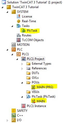
The MAIN program is called by the PlcTask task on a schedule defined in the PlcTask configuration. This is the point at which your program now has control of the runtime. From within MAIN, you have to call other programs that are part of your PLC project.
Note that the MAIN program is inside of a POUs folder. This is only Beckhoff’s default output generated by its wizard. Right now you could move the MAIN program into the GVLs folder and PlcTask would still call it without a problem.
Folders
In my programs I delete the DUTs, GVLs, POUs and VISUs folders and then I create my own folder structure that mimics the structure of the machine. For instance, if I was programming a multi-zone conveyor system, I would create folders called Zone01, Zone02, etc., and if I was programming a rotary assembly cell I would create folders such as RotaryTable, Station01, Station02, etc. Then, inside each folder I would put both the data structures and logic related to that part of the machine. There’s no need to separate the data from the logic in separate folders:
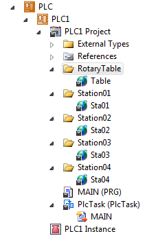
Note: the folders sort themselves alphabetically. It just so happens that “R” comes before “S” so it all worked out nicely above, but usually you want to enforce an ordering scheme. In that case, you can add a numerical prefix, such as “01_” to the beginning of every folder name to make them show up in the order you want. Also note that the current version of TwinCAT 3 doesn’t seem to sort properly as you add new content. To get it to sort properly, save everything, close the solution, and open it again.
You can also put folders inside of folders. For instance, if you have a zone-based conveyor system inside of the infeed side of your automation cell, you can put all of the zone folders inside of an Infeed folder.
Programs
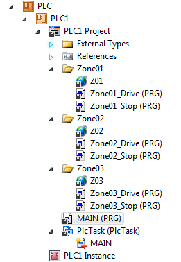
Within your new folder structure, add programs to control each logical element or function of the machine. For instance in a zone-based conveyor system, it’s typical for each zone to have a “drive” which is the motor that turns the rollers and a “stop” which is an air-actuated plunger that pops up to prevent a pallet from moving past a point, and drops down out of the way to allow the pallet to go forward. In a system like that, I would expect to see logic like this:
Always try to imagine someone trying to troubleshoot this machine. In a normal factory there will be a maintenance team that handles the maintenance on several different machines. Nobody will know any particular machine to the depth that you know it while you’re programming it. An operator might call them because there’s a pallet stuck in zone 2 and it won’t leave. If they open up the project above, they can quickly navigate to the Zone02 folder, open the Zone02_Stop program and find the output that drops the stop. If the output is on but the stop isn’t dropping, then they know there’s something wrong on the mechanical or electrical side with the stop, but if the output isn’t on in the program, then they can start working their way backwards through the logic trying to figure out why the program isn’t turning the output on.
You might wonder why you wouldn’t create a single function block and call it 3 times, one for each zone. Good question. Remember that even though the conveyor system appears to have 3 zones and they all looks the same, you should expect the logic for each zone to be slightly different. Remember that these are 3 separate physical parts of the machine and even though we might like to imagine that they’re identical, they’re not. If zone 1 is where material gets introduced to the line, then it likely has some kind of interface logic for interlocking with whatever is feeding it, such as a light curtain or a robot. Similarly the 3rd zone might need to be interlocked with some kind of pick-and-place equipment. If you create a function block that can handle the logic for all 3 zones, then you’ve complicated the logic for no real gain.
It’s better to see if you can pull out components of each zone that are necessarily identical (such as the stop) and create a function block for just that component. However, even then I would caution you that these are 3 separate physical stops and you should expect the logic to have to work slightly differently for each one, even if it’s something as simple as a timer. Also, it’s common that someone in maintenance might need to bypass some condition in the logic either to recover from an unforeseen problem or to bypass a broken sensor until it can be replaced. It’s much more difficult to do this if all 3 components share the same logic, since any bypassing code will likely affect all 3 stops, when in reality you only want to bypass a single sensor. Ultimately it’s your decision, but I suggest defaulting to the copy/paste method rather than the function block method in most cases.
Calling Program from MAIN
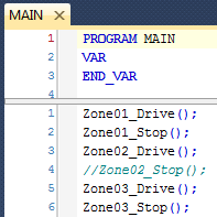
After you’ve created your programs, you need to “call” them once-and-only-once from your MAIN program. Here is what your MAIN program would look like in the conveyor example above:
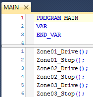
Remember that there is only one “instance” of each program (unlike a function block like a timer where there can be more than one instance). That means there is only one copy of the local variables declared inside of a program. If you call a program twice, you are executing the logic a second time, and it’s going to affect your local program variables and any global variables referenced by that program. That’s almost certainly not what you want. Someone reading your project will assume that every program is called once, and typically in the order that the programs are listed in the solution explorer, so please work hard to make the order that they show up and the order that you call them in match. If they need to be called in a certain order, please rename your programs and folders so that the ordering is the same.
Every time you create a new program you have to remember to call it from MAIN. If you don’t, the logic won’t execute and this can be difficult to debug. Thankfully, TwinCAT 3 will give you a hint that you made this mistake. As an example, I’m going to comment out the line where I call Zone02_Stop from the MAIN program:
The two forward slashes turn the line into a comment, which means anything after the slashes is ignored by the compiler. Now, right click on the PLC1 Project node in the Solution Explorer window and click Build from the context menu. After building, TwinCAT 3 will gray out any POUs that aren’t “linked,” which generally means any that aren’t called by your MAIN program:
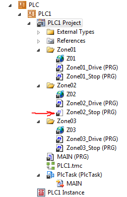
I highlighted the grayed out node with a red arrow above. Note that you can defeat this helpful feature by forcing the compiler to link it even if it’s not called. Click on the grayed out node, and then look at the Properties window:
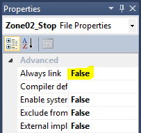
If you change the Always Link property from False to True, and then build the project, the node will no longer be grayed out. When you run the program it still won’t call this program, so you may wonder why this feature exists. Well, if the program isn’t linked, then that means the compiler didn’t even try to build it. There are certain cases where you might be trying to write some new logic and you don’t want to call it yet, but you do want to check if there are any compile errors. In that case you can set the Link Always property to True, build the project, and any compile errors will show up in the error list at the bottom of the screen. Just remember to change the property back to false so you will remember that you’re not calling this logic yet.
Program Variables
Each program has a variable declaration section at the top of it for local variables. Any variable that is only referenced by this program should go in the program’s local variables, not in a Global Variable List. That helps someone reading your program understand the “scope” of a variable. Global variables have more impact across your whole project and might even be referenced by your HMI program, but local variables should only be used by your program and modifying them should only have a local effect.
Note: In the latest version of TwinCAT 3, you can actually read and write program local variables from the HMI. I advise against doing this, but if you do, please make sure that you at least comment these variables in your program to let other people know that they’re accessed by the HMI. Even global variables accessed by the HMI need to be commented. That’s because it’s easy to find all the places where a variable is used in your program: just change the variable name and do a build. You’ll get compile errors at every reference (and there’s also a cross reference feature too). Unfortunately there’s no simple way to find places where that variable is referenced in the HMI, so make sure you make it obvious.
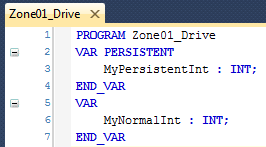
In addition to normal local variables, you can add a PERSISTENT variable section inside the variable declarations of a program, just like you would in a Global Variable List. The variables in a VAR PERSISTENT block will be saved and restored through a shutdown and a restart of the PLC runtime, just like persistent variables in a Global Variable List:
Less is More
How much logic should you put in a single program? My general rule of thumb is “as little as you can get away with.” You want all of the logic in a program to be “tightly coupled.” That is, all of the logic in a single program should be highly related to the other logic in there. Conversely, you want the logic in different programs to be “loosely coupled.” That is, ideally you want all the logic in a program to stand on its own without interacting with the logic in other programs at all.
Obviously this isn’t always possible, but in practice you want to reduce the coupling between programs. Since the coupling between programs takes place through global variables, this means you want to separate your logic in such a way that the interfacing signals between programs are few and simple. If you have a conveyor feeding a pick-and-place robot, then PickAndPlaceClearOfConveyor is a reasonable global variable that’s set in the pick-and-place logic and used in the conveyor logic. The conveyor logic shouldn’t “care” how that signal is created (that’s the job of the pick-and-place logic). It just needs to know that it’s clear so the conveyor can move.
In practice, I try to keep my programs between 1 and 12 rungs long, but that’s certainly not a hard and fast rule. Logic that needs to be longer should be longer. However, if your program logic really starts to grow, see if it’s really doing two things that could be separated out into two programs where just one or two global variables could handle the interaction between those two programs.
This chapter is part of the TwinCAT 3 Tutorial. Continue to the next chapter: Multiple Virtual PLCs.