The Mission Ladder Logic Programming Pattern is used for higher level decision making in a machine. While many machines are so simple that they only have one sequence of steps for their Automatic Mode, some are more complex.
A good example of such a complex machine is an Automated Storage and Retrieval System or AS/RS. This type of machine can perform several tasks, such as storing incoming bins of material in the storage racks, or picking up bins from storage and bringing them to an outgoing station. It’s typical to break these kinds of problems into smaller tasks, such as:
- Pick up bin from incoming station
- Place bin in storage location X
- Retrieve bin from storage location X
- Place bin in outgoing station
In the Mission pattern, each of these higher level tasks is called a “Mission”. The logic is responsible for choosing the appropriate mission to perform next, and monitor for the completion of that mission, or abort the mission if appropriate. Here is some typical Mission pattern logic:
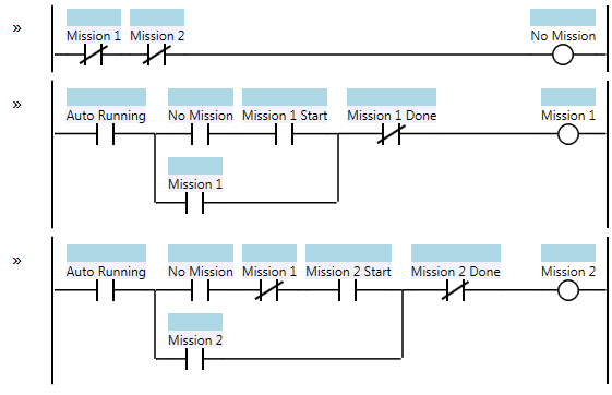
Mission
This is a system with only two missions, but as you can see it can be expanded to many more. One critical feature is that the logic must ensure that mutually exclusive missions are never active at the same time. In most cases this means that there is only one mission active at a time, but there are some systems where two different missions can overlap, if they don’t both need access to the same resources.
The Mission pattern is typically used with the Step pattern. Specifically, the Mission 1 coil becomes the Sequence Start condition for the Mission 1 sequence. Similarly, the Seq. Complete coil from the Step pattern becomes the Mission 1 Done condition in the logic above.
When organizing your ladder logic, consider putting the mission logic in a single routine, or ladder logic file. Then put the sequence logic for each individual mission in its own routine. Finally, put the low level logic that handles the control of each physical device in a routine named for that device. For example, one routine for a cylinder that extends and retracts, another routine for a motor that starts and stops, and a third routine for the temperature control logic for a heater. This is a good way to make your logic more “modular”, and it will help someone reading your program find the logic related to the device they’re interested in. So your ladder logic routines might look like:
- Choose Mission
- Mission 1 Sequence
- Mission 2 Sequence
- Locking Cylinder
- Hydraulic Pump
- Tank Temperature Control
More Patterns of Ladder Logic Programming.
Hi Scott!
Thank you for your work!
Actually I didn’t see difference between Step and Mission patterns. Can you point them?
@Andrei – The Mission pattern is responsible for choosing (typically) one mission out of many to perform next. So in the case of a material handling machine, you might have missions like “Pick from table A”, “Pick from table B”, “Place in Machine”, “Pick from Machine”, and “Place on Outfeed Conveyor”. Only one “mission in progress” bit should be on at any one time. So the mission pattern decides what job to execute next.
The Step pattern is for doing a sequential series of steps. So the steps for “Pick from Machine” would be something like “1. Move to Machine Pounce Position”, “2. Open Gripper”, “3. Move to Machine Pick Position”, “4. Close Gripper”, and “5. Move to Machine Pounce Position”.
Think of the Mission as “what to do” and the Step as “how to do it.”
Ok, I think I got it now, thanks! )
Hi Scott – just want to say thanks for publishing these articles. Stumbled across your site when looking up C vs Ladder Logic programming and have been reading your different articles for over an hour now! Great work!
Hi Scott,
I have a machine here with multiple missions and step sequences. One of the missions is to start a lamp. The mission drives a step sequence (the lamp startup procedure is quite complicated).
Question 1:
The lampStart mission that I’ve made is never “done”. it is always “inProgress”, because I don’t want the lamp to stop once it has reached the last step. In my step sequence, the final step “Complete” bit and the mission “done” bit NEVER come on. When the lamp is warmed up, the final step “inProgress” bit stays on. Is that how you would do it?
Question 2:
I have a safety bit and if it goes low, the lamp must stop. I have put this safety bit immediately before the “auto running” bit shown in your diagram above. Is that where you would put it? How do you normally exit a step sequence like this one?
@Rory – I would only use Missions to choose between alternatives where you can only run one of several missions at one time (such as choose which task a robot should do next). In this case, it sounds like you only have one resource (the lamp), so I wouldn’t use a mission controller for the lamp. I would just have a lamp sequence with a bunch of steps. In the case where you need to abort a sequence, I usually drop out the first two rungs (the in progress and done coils of the first step) and that will drop out all the remaining coils on the same scan.
On the third rung the
Mission 1
-|/|-
looks redundant with the
NoMission
-| |-
as NoMission is defined as a series with
Mission 1
-|/|-
in the series
???
@LLWJ – the PLC scans from top to bottom, so first it sets “No Mission”, then if on the second rung it sets “Mission 1” to ON, that doesn’t change the state of the “No Mission” coil (it will change on the following scan). If you don’t include the normally closed contact for “Mission 1” in the third rung, you can end up with both “Mission 1” and “Mission 2” coils on at the same time, which isn’t what you want.
Thanks for clearing that up. I was taking the the Ladder as if the calculations were happening instantaneously and not as a sequentially executed list of programming instructions
Provided it does not provide too much of a performance hit or use up all the program space, it would be clearer
(for my small mind) to recalculate NoMssn as a series of NoMssn1 – NoMssn2 – etc in between the individual Mssn code blocks. Other than the initial calculation of NoMssn1, it would result incode blocks that look exactly the same.
Like so for 3 missions:
   Msn1  Msn2  Msn3                              NoMsn1
---|/|---|/|---|/|--------------------------------( )---

  AutoRn   NoMsn1 Msn1Strt  Msn1done              Msn1
---| |---+---| |---| |---+---|/|------------------( )---
         |               |
         |   Msn1        |
         +---| |---------+


 NoMsn1  Msn1                                    NoMsn2
---| |---|/|--------------------------------------( )---

  AutoRn   NoMsn2 Msn2Strt  Msn2done              Msn2
---| |---+---| |---| |---+---|/|------------------( )---
         |               |
         |   Msn2        |
         +---| |---------+


 NoMsn2  Msn2                                    NoMsn3
---| |---|/|--------------------------------------( )---

  AutoRn   NoMsn3 Msn3Strt  Msn3done              Msn3
---| |---+---| |---| |---+---|/|------------------( )---
         |               |
         |   Msn3        |
         +---| |---------+
&&& Thanks Even More in general for these awesome Arduino Ladder Logic Programming Tools and this totally butt kick’n blog, You Rock Sir!!!
@LLWJ – I put the ladder in PRE tags and that seemed to work.
Your logic will work.
Note that in a system like Beckhoff TwinCAT 3 that has user-defined functions, I create a function called NoMission() that’s defined as Not(Msn1) AND Not(Msn2), etc. Then you can use the NoMission function in place of a contact, but since it’s a function it’ll re-evaluate it every time you call it. I think this gives you the best of both worlds.
Not every PLC has that feature, so for the pattern above I left it simple and explicit.
Thank you for your great articles.
Hi Scott,
I am programming a machine at the moment (total beginner here) and it needs a homing cycle whenever there is a power outage or failure.
After the homing cycle I just need to perform the regular cycle.
Can I see the homing cycle as some kind of mission which only need to happen once? Or does a homing cycle require a different kind of logic?
thank you for all the effort
Sven
@Sven – I typically put a Home All button on the main screen of the HMI, but the implementation can differ. If all the axes can home independently (at the same time) then you can just parallel the Home All PB around the regular manual Home PB for that axis. However, if one has to home before another, then you should create either a Home All Mission, or a special Startup Mode. In either case, you need to remember the case that you’re homing so the primary axis homes, and when it’s done then the second one homes.
When selecting a mission does the PLC program JSR the mission routine or does each mission routine have to have a reference in each rung that the mission is selected at the start of each rung?
Super useful well written tutorial, I’ve been using similar logics for years.
Also good points the in comments. I got screwed up badly in my early days by not realizing the need to re-evalutate the NoMission flag!
On Siemens i use an FC to re-evalutate on each rung.