The Step pattern is a Ladder Logic Programming Pattern that is the basic building block of a machine’s Automatic Mode. The logic for each Step is simple:
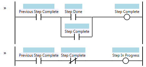
Step
You can combine any number of steps to form a Sequence. The steps will execute sequentially. When the Step In Progress coil turns on, this should be the signal to actuate a mechanism somewhere else in the program. For instance, if the Step is “Extend Cylinder” then a contact from the Step In Progress coil could be used to turn on the pneumatic valve to extend the cylinder. The Step stays active (i.e. the Step In Progress coil stays on) until the Step Done condition is true. In the example of extending the cylinder, the Step Done condition could be the Cylinder Extended input.
Consider that you might have several steps where you need to extend that cylinder. If you need to extend the cylinder in both Step 3 and Step 8, then your Extend Cylinder logic could have contacts from both Step 3 In Progress and Step 8 In Progress in parallel.
Here is an example of a two step sequence. Step 1 is “Extend Cylinder” and Step 2 is “Retract Cylinder”:
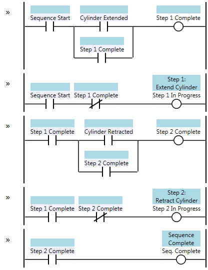
Two Steps
The Sequence Start condition is what initiates the sequence. This should be something like “the machine is in Auto Mode, an Auto Cycle is running, a part is present, and the part hasn’t been processed yet”. When the sequence is complete, then the Seq. Complete coil turns on. This can be used in combination with the Set/Reset pattern to latch a memory bit to indicate that the part has been processed. Presumably this causes another sequence to begin, such as an Unload Part sequence. Alternatively we might just wait for the operator to remove the part.
The Step pattern is frequently used with the Mission pattern. In this case the Sequence Start will be the Mission (in progress) coil and the Seq. Complete coil will signal the end of the mission.
Note that if the Sequence Start condition drops out during the sequence, then the entire sequence will reset (all the Complete coils will turn off, as will the Seq. Complete coil).
Also note that if the sequence starts and the cylinder is already extended, then the Step 1 In Progress coil will never turn on. It will jump directly to Step 2. In this case that might be what you want. If it’s not, you can consider putting the condition “Cylinder not Extended” in the Sequence Start condition. Another alternative is to force the Step In Progress coil to turn on for at least one scan before moving to the next step. This is relatively simple:
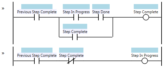
Step: Variant
By adding a contact for Step In Progress before the Step Done condition in the first rung, we make sure that the Step In Progress coil has to turn on for at least one scan before the step is complete. You can even take this form of the pattern and remove the Step Done condition:
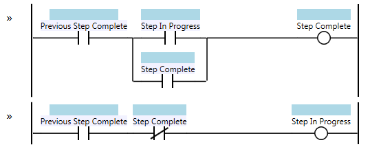
Step: One Shot
In this variant of the pattern, the Step In Progress coil turns on for exactly one scan. This makes it a “one-shot step”. A one-shot step is useful for doing part tracking and data logging since those things typically only require a single scan (such as set a bit, take a measurement, or record a value to the part history).
More Patterns of Ladder Logic Programming.
Great article for new ladder logic programmers or even a quick refresh for programmers who have been out of the loop for quite a while.
Thanks Gary! 🙂
Interesting article, thank you!
But what do you think about integer step pointer, like “Step_number”? This way we have only one variable to manage all the sequence.
@Andrei – I have several reasons for not using a step number:
You can insert an unlimited number of steps between any two steps using this method, but if you use a step number you would have to leave step numbers between them (such as step 10, 20, 30) and then you might run out of numbers and have to re-number.
Having a contact called StepOpenGripper is easier to read than an instruction where you say “if step number is 8”. Particularly for a technician troubleshooting it. If you have step numbers you need to document what each step number means.
This pattern allows you to have parallel branches, so I can tune my machine by overlapping steps. For instance, I’ve often had a sequence where you had to do one step, and then I had two sub-sequences (execute steps A and then B in parallel with steps C, then D, then E) and then after both sub-sequences were done I could execute another step. This is more difficult with a step number variable, because then you need step number variables for each sub-sequence, and that affects the things that are driven from the steps, such as trigger rungs elsewhere.
Also, this is “patterns of ladder logic”, so contacts and coils are more canonical than variables, move instructions, and equals instructions.
If you use a step number variable you’re basically making a state machine. The step pattern is more flexible than a state machine for the reasons I’ve described above.
Thank you Scott for such a comprehensive answer.
What do you think about “step mechanism” (what step actually does) place?
Do you put it in the same subroutine or you make different subroutine for it?
@Andrei – the step “in progress” coil is typically used to do one or more things during that step. The normal place to use a contact from an “in progress” coil is in the trigger rung of a Five Rung pattern.
In general, each physical part of a machine has a routine or program controlling just that part (so one routine for each motor, cylinder, etc.). A contact from the “in progress” coil should show up in that routine or program.
In addition to thinking “what does this step do” also think about “when does this such-and-such (e.g. motor) turn on”? From the perspective of someone troubleshooting a machine, they typically know what’s supposed to happen next (“why isn’t the motor starting?”) so they’re going to crack open the motor routine, find the Motor Start output and follow the ladder back from there.
On the other hand, they don’t necessarily know that you’re in the Turn on Motor step of your sequence (there could be more than one Turn on Motor step anyway) so they’re not likely to look there to start with. Since any given action/output can have more than one step affecting it, then putting the actions with the step tends to spread the logic related to a single output over multiple places, and that makes it harder to troubleshoot.
Thank you Scott, you have a really smart attitude for logic parts location. I appreciate your fast answers!
Hey,
I agree if you’r willingly only to use Ladder Logic Programming.
Sure these tutorials here are about Ladder Logic Programming patterns!
But as additional note: if you can handle some structured text, you should also consider using statemachines. You might underestimate the power of a finite statemachine (switch-case in combination with enums) (coded in structured text).
– enum = no instruction needed (like X = stepnumber 8)
– enum = no problem to add steps between
– enum = no reserve steps needed
– You don’t have to think about blocking other steps.
– branches can be handeld by splitting into to multible statemachines.
You spoke about Anitpatterns, I personally consider these old step patterns as kinda outdated, if you can use structured text.
But if I would be limited to Ladder Logic Programming, I would do it like you sugessted, (without step numbers, screw them!) .
Btw. Much Thanks for your tutorials!
Thanks mate.
@RaphaelVogt – if you’re working in structured text, then the equivalent is a state machine. I’m sure you can appreciate why I’m not going into structured text patterns in my “Patterns of Ladder Logic Programming” page. 🙂
I would also like to point out, as I did above, that this Step pattern gives you more flexibility than a state machine. Consider a sequence where you perform Step 1, and then you branch into 2 parallel sequences of steps, such as 2A1, 2A2 on one side and 2B1, 2B2, and 2B3 on the other side. When both sub-sequences are complete, then you execute Step 3. Not only is this easy with the ladder logic Step pattern, but it’s actually easy to change from a completely linear sequence to a partially parallel sequence later.
State machines, on the other hand, aren’t this flexible. A state machine, by definition, can only be in one stage, so it can’t simultaneously be in the 2A1 and the 2B2 state at the same time, at least not in an easily comprehensible way. You’d need to have 3 different stage machines – an overall one, and then two “child state machines”.
State machines, as I’ve said elsewhere, were at their heyday back when electrical engineers designed hard-coded logic with TTL chips using boolean gates. They used tools like Karnaugh Maps to express their state transitions and then reduce them to the minimum number of state bits so save on chip count. Therefore they suffer from the big-design-up-front anti-pattern. State machines are the anti-pattern, not steps. (Sometimes people confuse the Step pattern with Sequencers, and sequencers are definitely an anti-pattern – even more inflexible than state machines.)
Does this method allow a simple way to go back a step, or to skip steps?
For example, let’s say I want to run step 1, then 2, then 3, then go back to 2. Or if I want to go from step 3 to step 5, then 4, then 6.
Great tips in here Scott, they’re very helpful!
Quick question for you, or anyone else here for that matter. I can appreciate your approach in creating steps this way, but I’ve already created some programs utilizing Step Numbers. As you have said, this handcuffs the programmer a bit, and I’m currently going through the growing pains of that. Would you have any tips to tackling a project that was written utilizing Step Numbers, and converting to your proposed Step Pattern? I know that is a very vague and general question to ask, especially since all code is different. Just curious if you may have any pointers?
Thanks!
@Tom
The short answer is yes. This programming steps basically describe a grafcet. Which allows all jumps you can think of, as well as simultaneous “branchs” as Scott comments above.
Here’s a graphical example: http://www.cuvelier-ludovic.fr/images/graf16.gif
@Jesus
So how would I “go back” a step in the first ladder illustration above?
Let’s pretend it’s been extended to 3 steps. Once step 2 is complete (i.e. Step 2 Complete coil is sealed in), the only way I see for it to become incomplete (in order to execute it again) is if we lose the “Step 1 Complete” condition to unseal the coil.
However, if we turn Step 1 Complete off, then Step 1 will need to execute again and become complete in order for Step 2 to run.
How would you step back to 2 without re-running step 1?
@Tom – I’m going to take your question a step back (pun intended) and ask what it is you’re trying to accomplish. Sequences in machines are rarely trivially reversible (in my experience).
For example, let’s say I have a 3 step process: (1) turn on valve 1A, wait for axis 1 extended prox, (2) turn on valve 2A, wait for axis 2 extended prox, (3) turn on valve 3A, wait for axis 3 extended prox.
That’s assuming we have 5-rung logic for handling the extending and retracting of axes 1, 2, and 3.
Let’s assume that’s a mission called “Fully Extend”.
In that case, I’d expect another mission called “Fully Retract”: (1) turn on valve 3B, wait for axis 3 retracted prox, (2) turn on valve 2B, wait for axis 2 retracted prox, (3) turn on valve 1B, wait for axis 1 retracted prox.
You can skip a step. For instance if the “Fully Extend” mission was interrupted after step 2 and step 3 didn’t complete, then axis 3 might still be retracted. In that case your “Fully Retract” mission would skip step 1 because axis 3 is already retracted. You have to structure your missions and sequences so that either a mission won’t start if the sequence can’t handle it, or make the sequence capable of handling your starting state.
For a pick and place machine, it’s fairly easy to write sequences that can start from any condition, because you typically go “up” to a safe height, then go to your target position and do something, and going “up” is usually safe to do in all cases. On the other hand, with a 6-axis robot you could end up getting it into convoluted situations. Sometimes you write a home-from-anywhere routine which has a bunch of if-then statements that can get the robot out of all the different cases and go back to a known position, or you might even just give up and throw a fault and require an operator to recover manually.
Using the mission/sequence/step patterns, each mission exists to do only one thing. If you need to stop and do another thing, then abort this mission and start another mission.
TL;DR – in this pattern, you can’t reverse the sequence; you can just abort it and start again, and possibly skip steps.
@Scott,
What I have in mind is something like a compressor pressurizing a chamber.
Step 1 – Turn on the compressor and open a valve to start building pressure. Step is done when we hit X PSI
Step 2 – Close the valve and idle for a preset period of time. If time expires and PSI was maintained, step 2 is finished. However, if we lose some pressure and get below X PSI during this idle time, re-open the valve and start filling back up to X PSI (i.e. go back to step 1).
Should I have it refill “within” step 2 rather than trying to step back to step 1?
I should say, in my example you could simply restart the whole process, but let’s pretend these are really steps 11 and 12 in a long sequence, so going back to step 1 isn’t so simple
@Tom – I think you’re mixing “what to do” with “how to do it.” Make a routine or function block that regulates the pressure in the tank, and it’s input is a setpoint (in PSI). In your sequence, if you need one, Step 11 is “Pressurize Tank”. When you enter step 11, set the setpoint to the desired PSI. Step 11 is done when the pressure is within the desired range, for a certain amount of time. Assume the regulator logic will work and continue on with your sequence. If the pressure falls outside the acceptable range, then that’s a fault, and you can either abort or pause the sequence until the situation is corrected.
Hey!
Thank you for a great website!
I have a question:
I have seen that you use a “Fault timeout”-timer in your five rung pattern.
Shouldn’t every step in the “Step pattern” also have such a timer to indicate if a step has taken an unreasonable amount of time to complete?
@Josef – as long as whatever is performing the action that the step is triggering has a timeout, then you don’t need one in the step. When you walk up to the machine and it has a fault, it’s nice if the logic is still in the state it was in when the fault happened. That means it’s still in the “Extend Axis A” step, so you know what it was doing, and the “Extend Axis A” five-rung is faulted. Remember that there might be many steps in your program that extend axis A, but by leaving the step active you’ll know where it is in the sequence.
Okay, that makes sense.
Thanks for the quick answer
Could you give a brief example or a bit more detail on what the parallel branch would look like. I’ve done a few sequencers in the past but oddly never involving a parallel sequence.
-thank you for your most excellent efforts
@Kurt – really it’s just a matter of changing the Previous Step Complete contact to something else. If you want to branch out (for example after Step 1 you want to execute Step 2A and Step 2B in parallel) then the Previous Step Complete contacts for both 2A and 2B would be Step 1 Complete. Similarly, if you then want to merge two branches (for example, Step 3 happens after Step 2A and 2B are done) then Step 3’s Previous Step Complete would be Step 2A Complete and Step 2B Complete (in series).
When combining the Step pattern with the 5-rung pattern, how often do you find that the “In-Position” bit is the same as the “Step Done” bit? Is this redundant, or beneficial because it helps to further simplify the logic by decoupling variables and control levels?
I often find there are many, many manners in which actions can be initiated, and struggle to discern what is the most robust and also the most simple method for accomplishing a task.
@Brandon – Imagine a 4-step sequence: extend cyl A, retract cyl A, extend cyl A, retract cyl A. (This is because the part wouldn’t seat into the fixture properly and your boss says, “Did you try hitting it twice?”) I think that’s a good example why the In-Position bit for cylinder A extend can’t function as a step done bit in general. Whatever the In-Position bit is, you may want to do it multiple times in a sequence.
There’s another good reason… the Step Done bit is separately sealed in. Even if you have a simple two step sequence (extend cyl A, retract cyl A) then the In-Position bit for extend is going to turn off as soon as you execute your second step (because the cylinder would leave it’s extended position and the extended sensor would turn off).
That’s why I generally try to keep logical meanings separate and avoid trying to save a bit of logic here or there. Obviously if I was working with a processor with very limited memory, then my tune would change a little, but these days the logic space is practically unlimited.