This chapter is part of the TwinCAT 3 Tutorial.
In the Windows Server world, the big trend in the last 10 or so years has been server virtualization. That means we take one big beefy server and we run many “virtual servers” on that hardware. One physical server takes on the role of email server, file server, database server, etc., and we can logically think of each server as a separate entity because we can login to each one, see its disk drives, install programs, etc., but each virtual server shares the resources of the parent physical server. This revolution in the data center has also made its way into PLCs.
The TwinCAT 3 runtime running on a PC is kind of running a “virtual” PLC. That PLC runs in “ring 0” of Windows and handles all the tasks that a traditional PLC would, like scanning the I/O, and solving logic. TwinCAT 3 lets you create multiple virtual PLCs and run them all in the same TwinCAT 3 runtime. You might wonder why you’d want to do this. Here are some reasons…
Reason 1: Make use of Multiple Cores
The primary reason touted by Beckhoff is that this is how you make use of more than one core in those fancy new multi-core CPUs we can buy now. Modern CPUs in the Intel Core-i3, i5, and i7 series have 4 physical cores in the CPU, and each one can be executing a different program at the same time. However, the fundamental scheduled unit in Beckhoff, the “task”, can only run on a single core.
Even though the processor power available in a single core is much more than in a traditional PLC, EtherCAT is so fast that you may also be pushed to run your logic faster. In case you run out of CPU time, you now have the option of breaking your system up into multiple tasks that run on separate cores. In a typical system with a PLC and a motion controller, you can already do this by running your PLC task on one core and the motion control task on another. However, you still have the option of splitting your PLC logic into multiple virtual PLCs and running each one on a separate core so you can balance the loads.
Reason 2: Separation of I/O
Let’s say you have a really big system with lots of I/O. The more I/O you have, the longer it can take to scan the whole bus. Some day you might have a case where you want to scan a small portion of the bus very quickly (a high speed input, for example) but the rest of the I/O can be scanned at some more leisurely pace. The I/O scan matches its rate to the PLC task tied to it. That means you can accomplish multiple I/O scan rates by making one virtual PLC to handle your high speed I/O and another to handle the rest of it. TwinCAT will handle scanning just that portion of the I/O that each PLC needs for its I/O map.
Reason 3: Flexibility
In addition to allowing you to balance CPU load and I/O scan time, supporting multiple virtual PLCs also gives you the flexibility to move a virtual PLC to an entirely different physical machine.
Imagine you have three separate production cells (let’s call them OP10, OP20, and OP30). These form a production line where parts are transferred from one operation to the next. Currently the cells are beside each other in your facility, but they operate independently. Operators run parts through OP10, and they may or may not take the parts directly to OP20, or they might store them for a while and run them as batches. The point is that in the future the production department wants flexibility. They may want to install a transfer system to tie all the cells together, or they may want to batch the parts into bulk bins, possibly moving the cells away from each other physically. In today’s environment you may even see one of the operations contracted out to a lower tier supplier entirely, including moving the cell (say OP10) to their facility.
When you build and install this machine, if you separate the operations onto 3 virtual PLCs, you have the flexibility to run all 3 on a single physical PC (saving money). Later, when they want to move OP10 to another location, or even another facility, you just have to move the PLC and I/O for OP10 over to another PC (possibly a new PC, or possibly an existing PC in the new location). This is just a configuration change and a matter of plugging the EtherCAT cable for OP10 into a different EtherCAT master.
Reason 4: Modularity and Code Re-use
We often try to design our machines with re-usable components. If you’re a machine builder and the machines you sell have an optional feature, such as an auto-pallet-changer on a CNC mill, why ship that logic on a machine where the customer didn’t order it? If you use a separate virtual PLC to control your pallet changer, then you just don’t include that virtual PLC on machines that don’t have it. You might also be able to offer your pallet changer as an add-on for other CNC mills, perhaps ones you didn’t even build, by running your virtual PLC on a low-cost shoebox style TwinCAT 3 box without the overhead of an industrial PC.
What if you already have a bunch of TwinCAT 3 machines in your facility and you want to add a new plant-wide data collection system to all of them? Create a single virtual PLC project that handles the data collection and run it on all your TwinCAT 3 machines. That’s a lot simpler than modifying the logic on every single machine, and it keeps the data collection logic nice and isolated from the machine control logic. The machine control virtual PLC would interface with the data collection virtual PLC over mapped I/O which creates a nice clean interface between the two.
Example: Create Multiple PLCs
Start by creating a new TwinCAT XAE project called TwinCATMultiplePLCs:
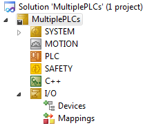
In this example we’re going to imagine two separate physical work cells called OP10 and OP20 each controlled by a separate virtual PLC. There will be a single physical EtherCAT master (though you could connect each work cell to its own physical EtherCAT master if you want). At first these two PLCs won’t communicate with each other, but we’ll add interlocks between them at a later stage of the example.
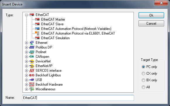
Let’s start by creating the I/O. Under the I/O node, right click on Devices and select Add New Item… from the context menu. That will open the Insert Device dialog. Select EtherCAT Master as the new device and enter EtherCAT in the name box:
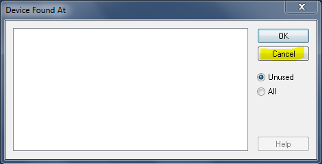
It will now try to attach this EtherCAT master to a physical device on your PC. If none exists (because you haven’t installed one), just click Cancel:
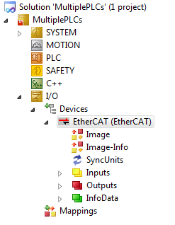
Now you will see your new EtherCAT master in the Solution Explorer:
Right click on the EtherCAT master and choose Add New Item… from the context menu. That will display the Insert EtherCAT Device dialog:
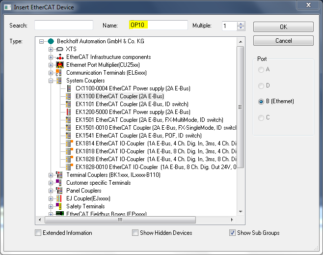
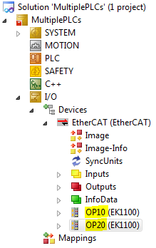
It will helpfully auto-select the EK1100 head module, which is what we typically want. Enter OP10 as a name for this device in the name box. This will be the head module for the I/O in the OP10 panel. Click OK. Now follow the same procedure again, but this time add an EK1100 with the name OP20. You will see these two new devices under your EtherCAT master:
Now under each head module we want to create a single input card. Right click on the OP10 device and choose Add New Item… from the context menu. The dialog will auto-select the last thing you selected. We want to add an EL1008 input card. The fastest way to select it in the list is to use the Search box. Type el1008 in the search box:
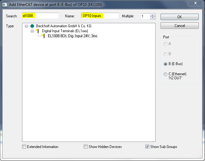
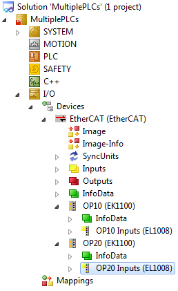
Enter a name for this card as well. I chose OP10 Inputs here, but you could choose something like OP10 In01 if you expect to add more cards. Click OK. Now follow the same procedure but for the OP20 device, to add a new card called OP20 Inputs. Your I/O should now look like this:
Now let’s add our virtual PLCs. Right click on the PLC node in the Solution Explorer and choose Add New Item… from the context menu. From the dialog that pops up, choose Standard PLC Project, enter OP10 in the name box, and click the Add button:
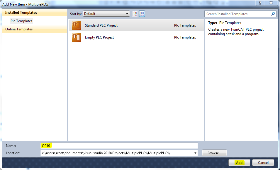
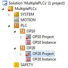
Wait for the wizard to create your new PLC project. Now repeat the process and create a second PLC project called OP20. You should see your two PLC projects under the PLC node:
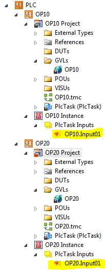
Now we need to create some inputs in our PLCs. I’ve already covered adding global variable lists earlier, so I’m only going to explain the broad steps here.
- Create a Global Variable List in the OP10 PLC called
OP10 - Create a Global Variable List in the OP20 PLC called
OP20 - Add a single
BOOLinput to each Global Variable List - Right click on the OP10 Project node and choose Build from the context menu
- Right click on the OP20 Project node and choose Build from the context menu
Now each PLC project will have an input for linking to the physical I/O:
Now go back down to your I/O. Expand the OP10 Inputs device (the EL1008 card) and then expand the Channel 1 node underneath that:
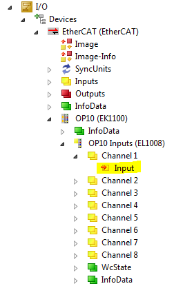
Underneath the Channel 1 node you’ll see a single node called Input. Right click on the Input node and choose Change Link… from the context menu. Now you’ll see the Attach Variable Input dialog:
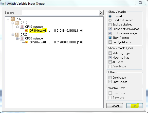
Select the OP10.Input01 variable in the tree and click the OK button. Now you’ve “mapped” the PLC input to the actual physical I/O. Repeat this procedure to map the OP20.Input01 variable to the OP20 Inputs Channel 1 physical I/O.
Now go up to the OP10 node under PLC, right click on it and choose Activate Boot Project…
Then do the same with the OP20 node under PLC. Also right click on the OP20 node and make sure that Autostart Boot Project is checked (the OP10 one should already be checked by default).
Since this is a new project we’ve created, we have to configure our Real-Time again. Under the SYSTEM node, double-click on the Real-Time node to show the real-time settings:
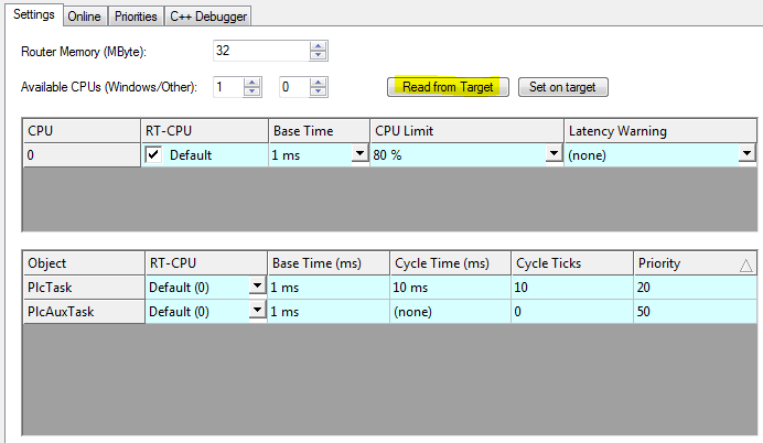
Click the Read from Target button (highlighted above). Assuming you already completed the Quickstart section earlier, then it should read the following configuration:
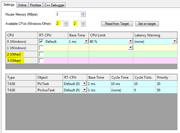
There are 2 cores assigned to Windows and 2 cores assigned as “Other.” Under the RT-CPU column, check CPUs 2 and 3, and uncheck CPU 0:
Now if you try to Activate Configuration to start your PLCs, it won’t work because the EtherCAT master isn’t linked to a physical Ethernet card. You can try it if you want, but you’ll just get an error message when it tries to start the runtime in run mode. To get around this, right click on the EtherCAT master node and choose Disable from the context menu. Now you can go to the TwinCAT menu (at the top of the screen) and choose Activate Configuration from the drop down menu. Click through the dialog boxes, just like in the Quickstart, earlier. When it asks if you want to restart in run mode, say Yes.
Going Online
You can still go online with each PLC, but it’s important to understand that you go online with each PLC separately. That means when you login with an online change, you’re making the change to that PLC only. There’s no way to simultaneously make online changes to 2 PLCs at the same time (however that should rarely ever be a problem).
ADS Ports
By default, the first PLC listens on ADS port 851. You can see this by double-clicking on the OP10 node. Subsequent PLCs are assigned in order, so the OP20 PLC uses ADS port 852, and so on. This is important if you make use of the free ADS DLL to communicate with the PLC(s) from a Windows program.
Running the PLCs on Separate CPU Cores
In the example above, there’s still only one task (called PlcTask) that executes both PLCs. Currently both PLCs are running on CPU 2 (i.e. core 2). If we want to run the two PLCs on separate CPU cores (say cores 2 and 3) then we need to have two PLC tasks.
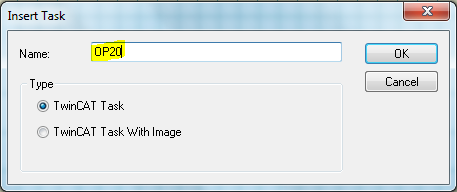
Under the SYSTEM node in the Solution Explorer, under the Tasks node double-click on the PlcTask node. In the name box, change the name of the task to OP10. Now right click on the Tasks node and choose Add New Item… from the context menu. In the Insert Task dialog, enter OP20 as the new task name, and click OK.
That will add a new OP20 node under Tasks. Double-click on the OP20 node and change the priority to 21. By default, new PLC tasks are assigned a priority of 20. Two tasks can’t have the same priority, so while we’re leaving the OP10 task as priority 20, we’re assigning the OP20 task to a priority of 21.
Now under the OP20 Project node, find the PlcTask node:
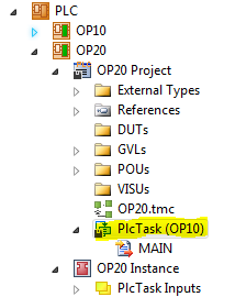
Notice that it’s still linked to the original OP10 task. Right click on the PlcTask node and and click Assign to Task from the context menu. That will display the Assign new Task dialog box:
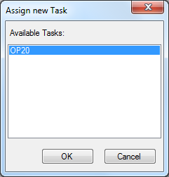
The only other option is the OP20 task, so click OK.
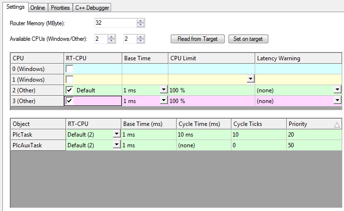
Go back under the SYSTEM node in the Solution Explorer and double-click on the Real-Time node:
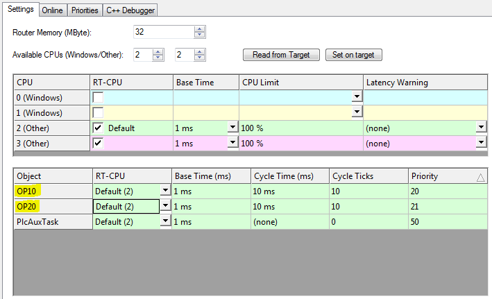
Notice that both the OP10 and OP20 tasks are listed in the bottom grid, but both are still assigned to CPU (core) 2. In the RT-CPU column of the bottom grid, in the OP20 row, click the drop-down box and change it to CPU 3:
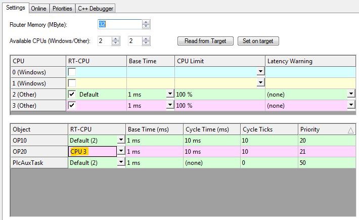
Now choose Activate Configuration from the TwinCAT menu at the top of the screen, and restart in run mode when it asks you. Now the OP10 PLC is running on CPU (core) 2 and the OP20 PLC is running on CPU (core) 3.
Click on the Online tab:
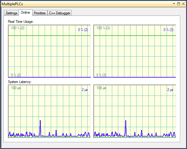
The two left-hand graphs are for CPU 2, and the right-hand graphs are for CPU 3. The top graphs show how much of the CPU you’re using (0% in this case because we didn’t run any logic). The bottom graphs show how the latency between when the timer interrupt fires (every 1 ms in our example) and when the task actually gets to run.
Connecting Virtual PLCs
In the example above, each PLC operates independently of the other. OP10 is blissfully unaware of the existence of OP20 even though both share an EtherCAT master, and could even share an input mapped from the same physical input.
What if we want to connect these two PLCs together so they can send signals back and forth? This is as simple as defining an input variable in one PLC, an output variable in the other (of the same type) and linking them together the same as if you were linking these variables to physical I/O.
For example, in OP10‘s Global Variable List define a variable like this:
ToOP20 AT %Q* : BOOL;
Then in OP20‘s, define:
FromOP10 AT %I* : BOOL;
Right click on each of OP10 Project and OP20 Project and select Build from the context menu. Now link the output from OP10 to the input from OP20:
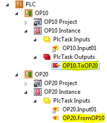
Right click on the OP10.ToOP20 PLC output (highlighted) and choose Change Link… from the context menu. Select OP20.FromOP10 in the Attach Variable dialog. Click OK.
Select Activate Configuration from the TwinCAT menu and say yes to restarting in run mode.
Now the OP10 PLC can send a signal to OP20. You can open both Global Variable Lists, go online with each one, and set the output variable to TRUE on the OP10 side and watch it change to TRUE on the OP20 side.
Sharing a Common Library
It’s normal to have a list of functions or function blocks you’d like to use in all your programs. Rather than copying the logic manually into each PLC project, TwinCAT 3 offers the ability to create a library and reference it in your other projects.
Typically you would create this library in another separate solution, but I like to have everything in one solution if I can. Start by right clicking on the PLC node in the Solution Explorer and choosing Add New Item… from the context menu. In this case select Empty PLC Project and give it the name CommonLibrary. Click Add.
The next thing you want to do is right click on the new CommonLibrary node and choose Disable from the context menu.
Now let’s add a function. Right click on the CommonLibrary Project node and select Add->POU from the context menu. In the dialog, set the name to DegreesToRadians, select Function as the type, REAL as the return type, and choose Structured Text (ST) as the language:
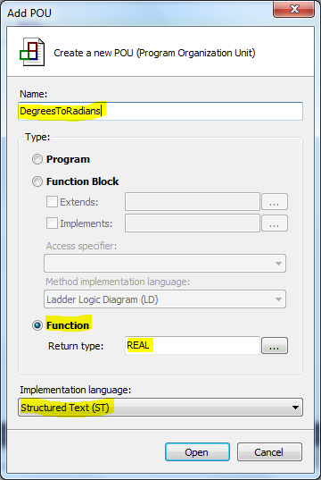
Then click Open. The formula for converting degrees to radians is to multiply by pi and then divide by 180. The mathematical constant PI is defined in a TwinCAT 3 library, which we will have to reference. Under CommonLibrary Project, right click on the References node and choose Add Library from the context menu. Expand the System section in the tree and choose the Tc2_System library and click OK.
Now define the DegreesToRadians function:
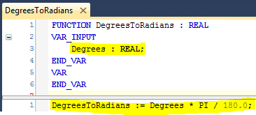
Note that there’s an input (Degrees), and one line of logic.
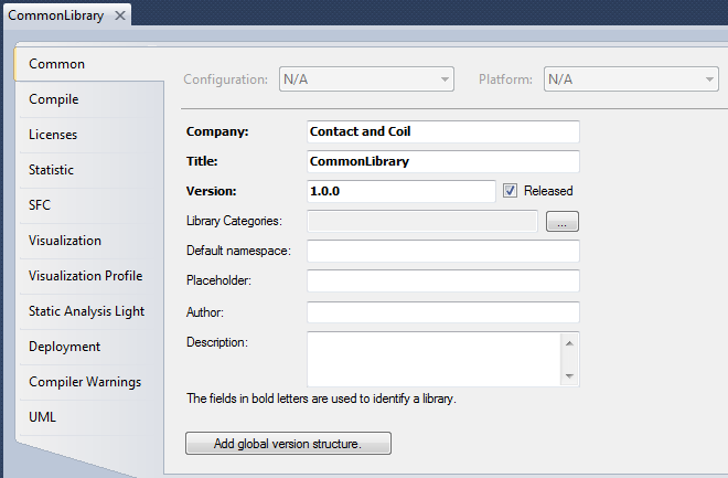
Before we can save it as a library, we have to set some properties. Right click on the CommonLibrary Project node and choose Properties from the context menu. Now you’ll see the properties window. You have to fill in the 3 bolded fields: Company, Title, and Version:
To access this function in the OP10 and OP20 PLCs, we first have to save this as a library, install it in the local library manager, and then reference it in both PLCs. Start by right-clicking on the CommonLibrary Project node and choosing Save as library and install… from the context menu. It will ask you to save this as a .library file somewhere on disk. It really doesn’t matter where you save it, as it will install it in the library manager immediately afterwards.
Now you can go under the OP10 Project node, right click on References and choose Add library… from the context menu. Your new library will show up under (Miscellaneous). Select it and click OK. Do the same thing under the OP20 Project node.
Now you can use the DegreesToRadians function in both virtual PLCs. If you want to modify the CommonLibrary then you have to remember to right click on the CommonLibrary Project node and choose Save as library and install… from the context menu. The library manager will reload it in both of your PLC projects. You’ll still have to login with an online change on the actual PLC to send the new logic to the runtime.
That concludes this section on multiple virtual PLCs. This is an advanced feature of TwinCAT 3, but it’s useful in many real-world applications.
This chapter is part of the TwinCAT 3 Tutorial. Continue to the next chapter: Ladder Logic Editor.