This Ladder Logic Programming Pattern stumps most novices, especially if they don’t really “get” ladder logic. How do you make a light flash on and off once per second? Here is the two-timer variant of the Flasher pattern:
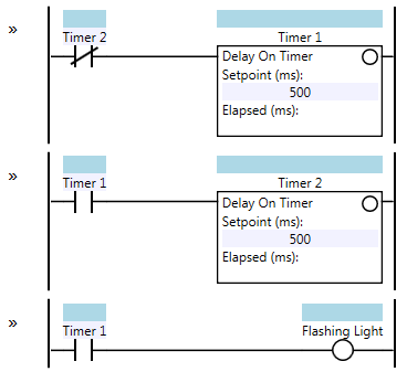
Flasher – Two Timer Variant
Here’s how it works: initially both timers are off, and their elapsed time values are set to zero. Timer 1 starts timing immediately. After 500 ms, Timer 1 is done timing and its output contact (sometimes called “done bit”) turns on. When this happens, Timer 2 starts timing, and the Flashing Light coil turns on as well. After another 500 ms, Timer 2 is done timing and its output contact turns on. On the next scan, this causes the rung input condition to Timer 1 to turn off, which immediately resets Timer 1, which means Timer 1’s output contact also turns off, resetting Timer 2 on the same scan and also turning off the Flashing Light coil. Now both timers are off, so on the next program scan Timer 1 will start timing again and the cycle repeats. Here’s an example timing diagram:
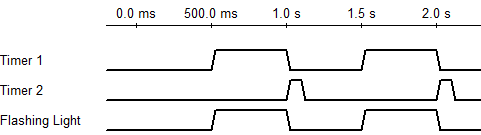
Some things to note: the Flashing Light turns on during the second half of the cycle (i.e. it starts off for 500 ms and then turns on for 500 ms). If you want the Flashing Light coil to be on initially, change the Timer 1 contact in the third rung from normally open (N.O.) to normally closed (N.C.).
Timer 2’s output contact only stays on for one program scan. That means it acts like a one-shot or a pulse. Program scan times can vary widely in PLCs. Older PLCs with slow processors and long ladder logic programs can have scan times in the hundreds of milliseconds. Newer PLCs have typical scan times in the tens of milliseconds, and PC-based PLCs like Beckhoff’s TwinCAT might have scan times in the sub-millisecond range. This is important because it affects the repeatability and accuracy of your timers. If your PLC has a 250 ms scan time then the period of the Flashing Light coil in the above example will vary anywhere from 1000 ms to 1500 ms. That’s because each timer is going to vary from 500 to 750 ms. If the program scan time is 10 ms, then the Flashing Light coil’s period will range from 1000 ms to 1020 ms (which is much more reasonable).
If you need your timers to be more accurate than this, then you’ll have to dig into the documentation of your PLC. You may be able to create a “high speed task” that runs more often than the main program. Typically this higher speed task would be driven by a timer interrupt which preempts the main logic.
The two-timer variant of the Flasher pattern shown above isn’t the only way to do this. There is a one-timer variant that is just as simple to understand, and has the advantage of being a little shorter:
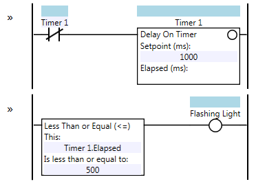
Flasher – One Timer Variant
Note that the Flashing Light coil will initially be on, and will turn off when Timer 1’s elapsed value exceeds 500 ms. You can reverse this by changing the Less Than or Equal instruction to a Greater Than instruction. Here’s a timing diagram of the one-timer variant:
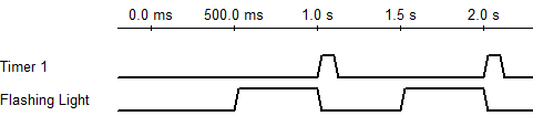
This one-timer variant reduces the inaccuracy of the timer from two scan times to one. For instance, if your PLC has a scan time of 250 ms, the one-timer variant’s Flashing Light coil will have a period ranging from 1000 ms to 1250 ms. That’s significantly better than the two-timer variant.
Also note that the self-resetting timer pattern (Timer 1 resets itself and then immediately starts timing again) is actually creating a one-scan pulse every one second. This is a pattern in itself that you may see used for other purposes.
More Patterns of Ladder Logic Programming.
feeling kinda silly that I couldn’t figure out the first approach on my own.
I had all kindsa rungs that would almost get me what I wanted.
I probably waited too long to google the solution…
Thanks for this, brother!
Hi
Thanks for sharing.
Please let me explain that such circuit can never function:
The moment at which coil of T2 charges the status of N.C of its switch contact rapidly flips from N.O to again N.C:
This instantaneous change cannot be adapted in electro-mechanical equipment, causing both timers to repeatedly switch on/off. There is a bogus effect of self latching. The circuit will continuously reset causing all of its switches to go gratata tatata tatata.
Such circuitry must be held using a specific types of timers containing an external DC battery to operate during the on/off states of T2: instead of an immediate state of N.C to N.O thr circuit based on 24H timer will relax, takes enough time to change state.
Either this or other sort of solid state technology must be invovled within.
I tried a similar circuit (traffic light signs) years ago using only delay on timers and relays: it fails. To be noticed that using a computer based simulator, the circuit runs fine (as there are no moving part in it)
I hope to have larger technical conversations here
All the best
Khaled
Khaled,
The timers are internal to the PLC. There will be no issues with the circuit. It is not noted but the T1 NO contact is a T1.DN bit as well as the T2 NC contact. T1 begins timing. Once T1 is done timing the output bit turns on and causes T2 to begin timing. Once T2 is done timing, the T2 output turns on. This turns T1 off and resets it. Because T1 is now off, T2 turns off and resets. Because T2 is off, T1 can now begin timing. The cycle now starts over. Using the T1 NO contact, it will flash the light since the T1 output is on every 500ms for 500ms.