Tag Archives: ladder-logic

Ladder Logic running on an Arduino UNO

Happy Canada Day!

Some of you may wonder if I’d fallen off the face of the Earth, but the truth is life just gets busy from time to time. Just for interest’s sake, here’s my latest fun project: an Arduino UNO running ladder logic!

Ladder Logic on a UNO

You may remember I wrote a ladder logic editor about 5 or so years ago called SoapBox Snap. It only had the ability to run the ladder logic in a “soft” runtime (on the PC itself). This is an upgrade for SoapBox Snap so that it can download the ladder logic to an Arduino and even do online debugging and force I/O:

Arduino UNO Ladder

I haven’t released the new version yet, but it’s very close (like a few days away probably).

Edit: I’ve now released it and here is a complete tutorial on programming an Arduino in Ladder Logic using SoapBox Snap.

Functional Programming in Ladder Logic

There’s a lot of stuff that falls under the term “functional programming,” but I’m just going to focus on the “functional” part right now, meaning when you define the value of something as a function of something else.

In ladder logic, we define the values of internal state (internal coils or registers) and outputs. We define these as functions of the inputs and internal state. We call each function a “rung”, and one rung might look like this:

Ladder diagram of Inputs A and B, and Internal State C

There’s something slightly odd going on in that rung though. You might say that we’ve defined C recursively, because C is a function of A, B, and itself. We all know, of course, that the PLC has no problem executing this code, and it executes as you would expect. That’s because the C on the right is not the same as the C on the left. The C on the right is the next state of C and the C on the left is the previous state of C.

Each time we scan, we redefine the value of C. That means C is an infinite time-series of true/false values. Huh?

Ok, imagine an array of true/false (boolean) values called “C”. The lower bound on the array index is zero, but the upper bound is infinite. C[0] is false (the value when we start the program). Then we start scan number 1, and we get to the rung above, and the PLC is really solving for is this:

Ladder logic defining C[1] as a function of A, B, and C[0]

If that were actually true (if it had an infinite array to store each coil’s value), then the ladder logic would be a truly functional programming language. But it’s not. Consider this:

Two ladder logic rungs with inputs A and B, internal coil C, and output D

In all modern PLCs, the first rung overwrites the value of C, so the second rung effectively uses the newly computed value for C when evaluating D. That means D[1] is defined as being equal to C[1] (the current state value of C). Why is this weird? Consider this:

Two previous rungs with the rung order reversed

By reversing the order of the rungs, I’ve changed the definition of D. After the re-ordering, D is now defined as C[0] (the previous state value of C) rather than C[1]. This isn’t a trivial difference. In an older PLC your scan time can be in the hundreds of milliseconds, so the D output can react noticeably slower in this case.

In a truly functional language, the re-ordering either wouldn’t be allowed (you can’t define D, which depends on C, before you define C) or the compiler would be able to determine the dependencies and re-order the evaluation so that C is evaluated before D. It would likely complain if it found a circular dependency between C and D, even though a PLC wouldn’t care about circular dependencies.

There are a few of reasons why PLCs are implemented like this. First, it saves memory. We would have to double our memory requirements if we always wanted to keep the last state and the next state around at the same time. Secondly, it’s easier to understand and troubleshoot. Not only does the PLC avoid keeping around two copies of each coil, but the programmer only has to worry about one value of each coil at any given point in the program. Third, the PLC runtime implementation is much simpler. It can be (and is) compiled to a kind of assembly language that can run efficiently on single threaded CPUs, which were the only CPUs available until recently.

Of course this comes with a trade-off. Imagine, for a moment, if rung-ordering didn’t matter. If you could solve the rungs in any order, that means you could also solve the rungs in parallel. That means if you upgraded to a dual-core CPU, you could instantly cut your scan time in half. Alas, the nature of ladder logic makes it very difficult to execute rungs in parallel.

On the other hand, we can still enforce a functional programming paradigm in our ladder logic programs if we follow these rules:

  • Never define a coil more than once in your program.
  • Don’t use a contact until after the rung where the associated coil has been defined.

That means there should only be one destructive write to any single memory location in your program. (It’s acceptable to use Set/Reset or a group of Move instructions that write to the same memory location as long as they’re on the same or adjacent rungs).

It also means that if coil C is defined on rung 5, then rungs 1 through 4 shouldn’t contain any contacts of coil C. This is the harder rule to follow. If you find you want to reference a coil before it’s defined, ask yourself if your logic couldn’t be re-organized to make it flow better.

Remember, someone trying to solve a problem in a PLC program starts at an output and uses cross references to move back through the program trying to understand it. Cross referencing from a contact to a coil that moves you forward in the program doesn’t require any logical leaps, but cross referencing to a coil later in the program means you need to logically think one scan backwards in time.

Benefits

While ladder logic isn’t a truly functional language, you can write ladder logic programs in the functional programming paradigm. If you do, you’ll find that your outputs react faster, and your programs are easier to understand and troubleshoot.

Ladder Logic vs. C#

PC programming and PLC programming are radically different paradigms. I know I’ve talked about this before, but I wanted to explore something that perplexes me… why do so many PC programmers hate ladder logic when they are first introduced to it? Ladder logic programmers don’t seem to have the same reaction when they’re introduced to a language like VB or C.

I mean, PC programmers really look down their noses at ladder logic. Here’s one typical quote:

Relay Ladder Logic is a fairly primitive langauge. Its hard to be as productive. Most PLC programmers don’t use subroutines; its almost as if the PLC world is one that time and software engineering forgot. You can do well by applying simple software engineering methods as a consequence, e.g., define interfaces between blocks of code, even if abstractly.

I’m sorry, but I don’t buy that. Ladder logic and, say C#, are designed for solving problems in two very different domains. In industrial automation, we prefer logic that’s easy to troubleshoot without taking down the system.

In the world of C#, troubleshooting is usually done in an offline environment.

My opinion is that Ladder Logic looks a lot like “polling” and every PC programmer knows that polling is bad, because it’s an inefficient use of processor power. PC programmers prefer event-driven programming, which is how all modern GUI frameworks react to user-initiated input. They want to see something that says, “when input A turns on, turn on output B”. If you’re familiar with control systems, your first reaction to that statement is, “sure, but what if B depends on inputs C, D, and E as well”? You’re right – it doesn’t scale, and that’s the first mistake most people make when starting with event-driven programming: they put all their logic in the event handlers (yeah, I did that too).

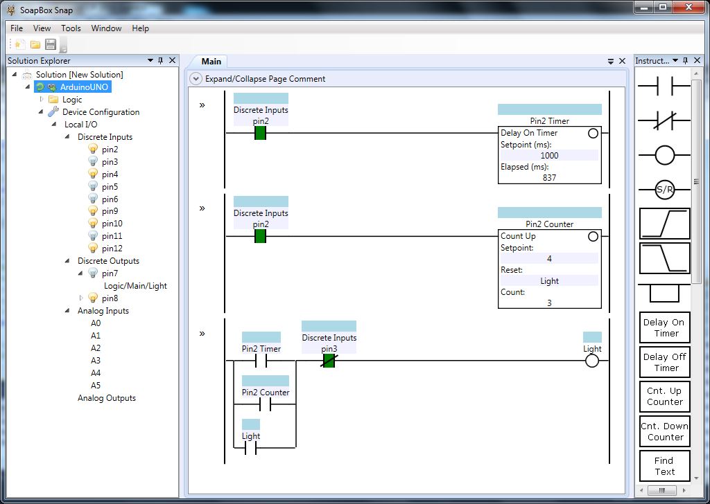
Still, there are lots of situations where ladder logic is so much more concise than say, C#, at implementing the same functionality, I just don’t buy all the hate directed at ladder logic. I decided to describe it with an example. Take this relatively simple ladder logic rung:

What would it take to implement the same logic in C#? You could say all you really need to write is D = ((A && B) || D) && C; but that’s not exactly true. When you’re writing an object oriented program, you have to follow the SOLID principles. We need to separate our concerns. Any experienced C# programmer will say that we need to encapsulate this logic in a class (let’s call it “DController” – things that contain business logic in C# applications are frequently called Controller or Manager). We also have to make sure that DController only depends on abstract interfaces. In this case, the logic depends on access to three inputs and one output. I’ve gone ahead and defined those interfaces:

    public interface IDiscreteInput
    {
        bool GetValue();
        event EventHandler InputChanged;
    }

    public interface IDiscreteOutput
    {
        void SetValue(bool value);
    }

Simple enough. Our controller needs to be able to get the value of an input, and be notified when any input changes. It needs to be able to change the value of the output.

In order to follow the D in the SOLID principles, we have to inject the dependencies into the DController class, so it has to look something like this:

    internal class DController
    {
        public DController(IDiscreteInput inputA, 
            IDiscreteInput inputB, IDiscreteInput inputC, 
            IDiscreteOutput outputD)
        {
        }
    }

That’s a nice little stub of a class. Now, as an experienced C# developer, I follow test-driven development, or TDD. Before I can write any actual logic, I have to write a test that fails. I break open my unit test suite, and write my first test:

        [TestMethod]
        public void Writes_initial_state_of_false_to_outputD_when_initial_inputs_are_all_false()
        {
            var mockInput = MockRepository.GenerateStub<IDiscreteInput>();
            mockInput.Expect(i => i.GetValue()).Return(false);
            var mockOutput = MockRepository.GenerateStrictMock<IDiscreteOutput>();
            mockOutput.Expect(o => o.SetValue(false));

            var test = new DController(mockInput, mockInput, mockInput, mockOutput);

            mockOutput.VerifyAllExpectations();
        }

Ok, so what’s going on here? First, I’m using a mocking framework called Rhino Mocks to generate “stub” and “mock” objects that implement the two dependency interfaces I defined earlier. This first test just checks that the first thing my class does when it starts up is to write a value to output D (in this case, false, because all the inputs are false). When I run my test it fails, because my DController class doesn’t actually call the SetValue method on my output object. That’s easy enough to remedy:

    internal class DController
    {
        public DController(IDiscreteInput inputA, IDiscreteInput inputB, 
            IDiscreteInput inputC, IDiscreteOutput outputD)
        {
            if (outputD == null) throw new ArgumentOutOfRangeException("outputD");
            outputD.SetValue(false);
        }
    }

That’s the simplest logic I can write to make the test pass. I always set the value of the output to false when I start up. Since I’m calling a method on a dependency, I also have to include a guard clause in there to check for null, or else my tools like ReSharper might start complaining at me.

Now that my tests pass, I need to add some more tests. My second test validates when my output should turn on (only when all three inputs are on). In order to write this test, I had to write a helper class called MockDiscreteInputPatternGenerator. I won’t go into the details of that class, but I’ll just say it’s over 100 lines long, just so that I can write a reasonably fluent test:

        [TestMethod]
        public void Inputs_A_B_C_must_all_be_true_for_D_to_turn_on()
        {
            MockDiscreteInput inputA;
            MockDiscreteInput inputB;
            MockDiscreteInput inputC;
            MockDiscreteOutput outputD;

            var tester = new MockDiscreteInputPatternGenerator()
                .InitialCondition(out inputA, false)
                .InitialCondition(out inputB, false)
                .InitialCondition(out inputC, false)
                .CreateSimulatedOutput(out outputD)
                .AssertThat(outputD).ShouldBe(false)

                .Then(inputA).TurnsOn()
                .AssertThat(outputD).ShouldBe(false)

                .Then(inputB).TurnsOn()
                .AssertThat(outputD).ShouldBe(false)

                .Then(inputA).TurnsOff()
                .AssertThat(outputD).ShouldBe(false)

                .Then(inputC).TurnsOn()
                .AssertThat(outputD).ShouldBe(false)

                .Then(inputB).TurnsOff()
                .AssertThat(outputD).ShouldBe(false)

                .Then(inputA).TurnsOn()
                .AssertThat(outputD).ShouldBe(false)

                .Then(inputB).TurnsOn()
                .AssertThat(outputD).ShouldBe(true); // finally turns on

            var test = new DController(inputA, inputB, inputC, outputD);

            tester.Execute();
        }

What this does is cycle through all the combinations of inputs that don’t cause the output to turn on, and then I finally turn them all on, and verify that it did turn on in that last case.

I’ll spare you the other two tests. One check that the output initializes to on when all the inputs are on initially, and the last test checks the conditions that turn the output off (only C turning off, with A and B having no effect). In order to get all of these tests to pass, here’s my final version of the DController class:

    internal class DController
    {
        private readonly IDiscreteInput inputA;
        private readonly IDiscreteInput inputB;
        private readonly IDiscreteInput inputC;
        private readonly IDiscreteOutput outputD;

        private bool D; // holds last state of output D

        public DController(IDiscreteInput inputA, IDiscreteInput inputB, 
            IDiscreteInput inputC, IDiscreteOutput outputD)
        {
            if (inputA == null) throw new ArgumentOutOfRangeException("inputA");
            if (inputB == null) throw new ArgumentOutOfRangeException("inputB");
            if (inputC == null) throw new ArgumentOutOfRangeException("inputC");
            if (outputD == null) throw new ArgumentOutOfRangeException("outputD");

            this.inputA = inputA;
            this.inputB = inputB;
            this.inputC = inputC;
            this.outputD = outputD;

            inputA.InputChanged += new EventHandler((s, e) => setOutputDValue());
            inputB.InputChanged += new EventHandler((s, e) => setOutputDValue());
            inputC.InputChanged += new EventHandler((s, e) => setOutputDValue());

            setOutputDValue();
        }

        private void setOutputDValue()
        {
            bool A = inputA.GetValue();
            bool B = inputB.GetValue();
            bool C = inputC.GetValue();

            bool newValue = ((A && B) || D) && C;
            outputD.SetValue(newValue);
            D = newValue;
        }
    }

So if you’re just counting the DController class itself, that’s approaching 40 lines of code, and the only really important line is this:

    bool newValue = ((A && B) || D) && C;

It’s true that as you wrote more logic, you’d refactor more and more repetitive code out of the Controller classes, but ultimately most of the overhead never really goes away. The best you’re going to do is develop some kind of domain specific language which might look like this:

    var dController = new OutputControllerFor(outputD)
        .WithInputs(inputA, inputB, inputC)
        .DefinedAs((A, B, C, D) => ((A && B) || D) && C);

…or maybe…

    var dController = new OutputControllerFor(outputD)
        .WithInputs(inputA, inputB, inputC)
        .TurnsOnWhen((A, B, C) => A && B && C)
        .StaysOnWhile((A, B, C) => C);

…and how is that any better than the original ladder logic? That’s not even getting into the fact that you wouldn’t be able to use breakpoints in C# when doing online troubleshooting. This code would be a real pain to troubleshoot if the sensor connected to inputA was becoming flaky. With ladder logic, you can just glance at it and see the current values of A, B, C, and D.

Testing: the C# code is complex enough that it needs tests to prove that it works right, but the ladder logic is so simple, so declarative, that it’s obvious to any Controls Engineer or Electrician exactly what it does: turn on when A, B, and C are all on, and then stay on until C turns off. It doesn’t need a test!

Time-wise: it took me about a minute to get the ladder editor open and write that ladder logic, but about an hour to put together this C# example in Visual Studio.

So, I think when someone gets a hate on for ladder logic, it just has to be fear. Ladder logic is a great tool to have in your toolbox. Certainly don’t use ladder logic to write an ERP system, but do use it for discrete control.

When to use a Sealed Coil vs. a Latch/Unlatch?

I just realized something I didn’t learn until at least a year into programming PLCs, and thought it would be a great thing to share for newer ladder logic programmers: when should you use a sealed-in coil vs. a latch/unlatch?

On the surface of it, a latch/unlatch instruction is sometimes frowned upon by experienced programmers because it’s correlated with bad programming form: that is, modifying program state in more than one location in the program. If you have one memory bit that you’re latching and unlatching all over the place, it really hinders readability, and I pity the fool that has to troubleshoot that code. Of course, most PLCs let you use the same memory bit in a coil instruction as much as you want, and that’s equally bad form, so I don’t take too strict of a stance on this. If you are going to use latch/unlatch instructions, make sure you only use one of each (for a given memory bit), and keep them very close together (preferably on adjacent rungs, or even in different branches of the same rung). Don’t make the user scroll, or worse yet, do a cross reference.

As you can imagine, if you’re going to use a Latch/Unlatch instruction and keep them very close together, it’s trivial to convert that to a rung with a sealed in coil, so what, if anything is the difference? Why have two sets of instructions that do the same thing?

It turns out (depending on the PLC hardware you’re using) that they act differently. On Allen-Bradley hardware, at least, an OTE instruction (coil) will always be reset (cleared to off) during the pre-scan. The pre-scan happens any time you restart the program, which is most importantly after a loss of power. If you’re using a sealed in coil to remember you have a pallet present in a zone, you’ll be in for a big surprise when you cycle power. All your zones will be unblocked, and you could end up with a bunch of crashes! On the other hand, OTL and OTU instructions don’t do anything during a pre-scan, so the state remains the same as it was before the power was removed.

For that reason, a latch/unlatch is a great indication of long term program state. If you have to track physical state about the real world, use a latch/unlatch instruction.

On the other hand, a sealed-in coil is a great way to implement a motion command (e.g. “attempting to advance axis A”). In that case you want your motion command to reset if the power drops out.

I hope that clears it up a bit. I always tried to avoid all latch/unlatch instructions until I understood these concepts.


Clean Ladder Logic

I’ve recently been reading Clean Code: A Handbook of Agile Software Craftsmanship. It’s written by Robert C. “Uncle Bob” Martin of Agile software (among other) fame. The profession of computer programming sometimes struggles to be taken seriously as a profession, but programmers like Martin are true professionals. They’re dedicated to improving their craft and sharing their knowledge with others.

The book is all about traditional PC programming, but I always wonder how these same concepts could apply to my other obsession, ladder logic. I’m the first to admit that you don’t write ladder logic the same way you write PC programs. Still, the concepts always stem from a desire for Readability.

Martin takes many hard-lined opinions about programming, but I think he’d be the first to admit that his opinions are made to fit the tools of the time, and those same hard-and-fast rules are meant to be bent as technology marches on. For instance, while he admits that maintaining a change log at the top of every source file might have made sense “in the 60’s”, the rise of powerful source control systems makes this obsolete. The source control system will remember every change that was made, who made it, and when. Similarly, he advocates short functions, long descriptive names, and suggests frequently changing the names of things to fit since modern development environments make it so easy to rename and refactor your code.

My favorite gem is when Martin boldly states that code comments, while sometimes necessary, are actually a failure to express ourselves adequately in code. Sometimes this is a lack of expressiveness in the language, but more often laziness (or pressure to cut corners) is the culprit.

What would ladder logic look like if it was “clean”? I’ve been visiting this question during the development of SoapBox Snap. For instance, I think manually managing memory, tags, or symbols is a relic of older under-powered PLC technology. When you drop a coil on the page in SoapBox Snap, you don’t have to define a tag. The coil is the signal. Not only is it easier to write, it prevents one of the most common cardinal sins of beginner ladder logic programming: using a bit address in two coil instructions.

Likewise, SoapBox Snap places few if any restrictions on what you can name your coils. You don’t have to call it MTR1_Start – just call it Motor 1: Start. Neither do you need to explicitly manage the scope of your signals. SoapBox Snap knows where they are. If you drop a contact on a page and reference a coil on the same page, it just shows the name of the coil, but if you reference a contact on another page, it shows the “full name” of the other coil, including the folders and page names of your organization structure to find it. Non-local signals are obviously not local, but you still don’t have to go through any extraneous mapping procedure to hook them up.

While we’re on the topic of mapping, if you’ve read my RSLogix 5000 Tutorial then you know I spend a lot of time talking about mapping your inputs and your outputs. This is because RSLogix 5000 I/O isn’t synchronous. I think it’s pointless to make the programmer worry about such pointless details, so SoapBox Snap uses a synchronous I/O scan, just like the old days. It scans the inputs, it solves the logic, and then it scans the outputs. Your inputs won’t change in the middle of the logic scan. To me, fewer surprises is clean.

I’ve gone a long way to make sure there are fewer surprises for someone reading a ladder logic program in SoapBox Snap. In some ladder logic systems, the runtime only executes one logic file, and that logic file has to “call” the other files. If you wanted to write a readable program, you generally wanted all of your logic files to execute in the same order that they were listed in the program. Unfortunately on a platform like RSLogix 5000, the editor sorts them alphabetically, and to add insult to injury, it won’t let you start a routine name with a number, so you usually end up with routine names like A01_Main, A02_HMI, etc. If someone forgets to call a routine or changes the order that they execute in the main routine, unexpected problems can surface. SoapBox Snap doesn’t have a “jump to page” or “jump to routine” instruction. It executes all logic in the order it appears in your application and each routine is executed exactly once per scan. You can name the logic pages anything you want, including using spaces, and you can re-order them with a simple drag & drop.

Program organization plays a big role in readability, so SoapBox Snap lets you organize your logic pages into a hierarchy of folders, and it doesn’t limit the depth of this folder structure. Folders can contain folders, and so on. Folder names are also lenient. You can use spaces or special characters.

SoapBox Snap is really a place to try out some of these ideas. It’s open source. I really hope some of these innovative features find their way into industrial automation platforms too. Just think how much faster you could find your way around a new program if you knew there were no duplicated coil addresses, all the logic was always being executed, and it’s always being executed in the order shown in the tree on the left. The productivity improvements are tangible.

On Readability

Programming both PCs and PLCs sometimes gets me thinking about programming from a higher level. I’ve written a lengthy answer over on StackOverflow about the differences between PC and PLC programming. What I haven’t talked about before is how they are the same.

First, let me define what I mean by PC and PLC programming. By PC programming, I’m generally referring to imperative programming. There are actually two popular PC programming paradigms: imperative and declarative, and the paradigm with new-found popularity, functional, is actually a subset of declarative programming.

How PC and PLC programming are NOT the same

Most PLC programming falls into the declarative category, and most PC programming falls into the imperative category. For examples:

PC:

  • Visual Basic, C/C++, C#: imperative
  • Lisp, F#: functional
  • HTML, XAML: declarative

PLC:

  • Ladder logic: declarative
  • Function block diagram: functional
  • Structured text: imperative

So normally when we talk about the differences between PC and PLC programming, we’re talking about the differences between imperative and declarative programming, but there’s obviously overlap on both sides of the fence.

The major difference, however, is audience. In North America at least, we write PC programs with the expectation that other programmers will have to read, understand and make changes to them, but we write PLC programs with the expectation that people in the maintenance department will be expected to go online with and troubleshoot our programs. Just think about how odd that would be in the PC world: when a word processor crashes, nobody whips out their debugger, figures out what caused the program to crash, makes a fix and continues writing their letter. Primarily this is because the source code doesn’t come with the word processor, but it’s also because the programming language can only be understood by programmers.

How PC and PLC programming ARE the same

When you look at what makes a PC program good or bad, on a high level it’s the same thing that makes a PLC program good or bad: readability. Now as I’ve pointed out, the people who have to read the program is different in each case, but really readability is the fundamental measure by which experienced programmers rate programs.

On the PC side ,the name of the game with readability is modularity. You want to divide up your program into parts, and you want to make those individual parts as self-contained as possible. You want to minimize the interaction to these parts as much as possible. That makes it easier to reason about the program because you’re abstracting away the underlying complexity on each piece and leaving a less complex interface that you can interact with. The entire domain of object oriented programming is an extension of the concept of modularity.

On the PLC side, readability is equivalent to being able to troubleshoot the machine when it’s down. Experienced PLC programmers ask themselves, “if this machine stopped unexpectedly and I had to figure out why it stopped, what would I do? How can I make it easier for someone following that process to figure out what’s wrong with the machine?”

It turns out that most people troubleshooting a machine follow a similar procedure: you start at the outputs and you work your way backwards. You generally have a good idea what the machine is supposed to do next (e.g. move slide A to position B). You can look at the print set, or even the valve itself and figure out what output should be turning on. You look at the indicator on the output card and it’s not on, so the logic isn’t telling it to turn on. You crack open the laptop, and you find that output. You’re looking for one thing: the COIL.

Notice the one big mistake you could make if you’re writing a program: you could use a whole bunch of set and reset (or latch and unlatch) instructions to drive your outputs. Based on my description, you can easily see why that would make the program less readable: which set instruction is the one that’s supposed to be turning on the output right now? If there’s only one, it’s easy, but if there are 10, you’re already lost.

Let’s assume you do find the coil that drives this output. Your next step is to follow the logic back through the rungs, right clicking on the conditions that aren’t satisfied and cross referencing until you understand what the machine is waiting for. What are some obvious mistakes you can make that would hinder this process?

  • Using an integer (or sequencer – yuck!) to store your automatic process step number rather than using individual coils for each step
  • Using set/reset or latch/unlatch instructions more than once on each bit
  • Using really long tag names so readers have to scroll left/right or up/down more than necessary to read one rung
  • Calling subroutines more than once per scan so you can’t see the state of the logic in the subroutine (newer controllers have function blocks where you can drill down into individual instances, which is nice)
  • Using For Loops – same reason
  • Having logic that is conditionally scanned – particularly in controllers where it isn’t obvious if the logic you’re looking at is scanned or not
  • Mapping your inputs or outputs by block copying them to or from a user defined type, word or array (Don’t make the reader start counting bits! The line is down!)

Once you start thinking from the point of view of someone troubleshooting the machine, your perspective on good vs. bad programming really changes. You realize that techniques that seem to save you time while you’re programming end up costing the company hours of lost production time while maintenance picks their way through your cryptic logic.

Next time you’re writing your ladder logic, think of the poor maintenance guy who has to figure out what’s wrong, and try to make his life a little less miserable.

Dogs, Cats and Moody Machines

Have you ever wondered what the ladder logic for a dog would look like?  I imagine it’s something like this:

ladder-logic-for-dog

… and so on.  I think that’s why we consider dogs so loyal.  Perhaps by loyal, we mean predictable, or understandable.

Ever wonder what the ladder logic for a cat would look like?  I imagine it thus:

ladder-logic-for-cat

… or something like that.  Actually I’m pretty sure I’ve met a couple of cats that came equipped with thirteen sequencers and a conditional subroutine jump in there somewhere.  It certainly makes life interesting.  Does that little tail wag mean it’s safe to pet, or does it mean your cat is about to mistake your inner thigh for prey?  Who knows!  What fun!

I guess my point is, cats can be moody, and believe it or not, so can machines.  You might call it “internal machine state”, but I call it moodiness.  Have you ever been trying to troubleshoot a machine and it was stuck thinking there was a part in one of the stations that really wasn’t there?  Every time it indexes it keeps faulting?  That’s machine moodiness.  So there you are, flagging every sensor in sight trying to get that part present bit to clear, and no matter how many roses or chocolates you buy for the darned thing, you know you’ll be sleeping in the dog house tonight.

Thankfully, there’s a cure for machine moodiness:  Make all internal state visible and editable.  At the very least, there should be a screen on the HMI that shows the current status of the part present bits at each station.  If you really want to be fancy, make sure it allows the operator to set and clear those bits manually.  That includes latches, sealed coils, counters, FIFOs, and even long running timers.

Anyway, if you can’t see it, you can’t troubleshoot it, so adding visibility will save you time in the future.  Trust me.  And trust dogs; they’re quite loyal.