There’s a lot of stuff that falls under the term “functional programming,” but I’m just going to focus on the “functional” part right now, meaning when you define the value of something as a function of something else.
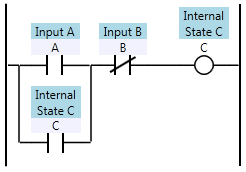
In ladder logic, we define the values of internal state (internal coils or registers) and outputs. We define these as functions of the inputs and internal state. We call each function a “rung”, and one rung might look like this:

There’s something slightly odd going on in that rung though. You might say that we’ve defined C recursively, because C is a function of A, B, and itself. We all know, of course, that the PLC has no problem executing this code, and it executes as you would expect. That’s because the C on the right is not the same as the C on the left. The C on the right is the next state of C and the C on the left is the previous state of C.
Each time we scan, we redefine the value of C. That means C is an infinite time-series of true/false values. Huh?
Ok, imagine an array of true/false (boolean) values called “C”. The lower bound on the array index is zero, but the upper bound is infinite. C[0] is false (the value when we start the program). Then we start scan number 1, and we get to the rung above, and the PLC is really solving for is this:
![ABC0C1 Ladder logic defining C[1] as a function of A, B, and C[0]](http://www.contactandcoil.com/wp-content/uploads/ABC0C1.png)
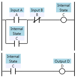
If that were actually true (if it had an infinite array to store each coil’s value), then the ladder logic would be a truly functional programming language. But it’s not. Consider this:

In all modern PLCs, the first rung overwrites the value of C, so the second rung effectively uses the newly computed value for C when evaluating D. That means D[1] is defined as being equal to C[1] (the current state value of C). Why is this weird? Consider this:

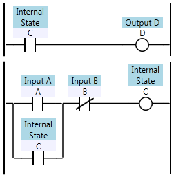
By reversing the order of the rungs, I’ve changed the definition of D. After the re-ordering, D is now defined as C[0] (the previous state value of C) rather than C[1]. This isn’t a trivial difference. In an older PLC your scan time can be in the hundreds of milliseconds, so the D output can react noticeably slower in this case.
In a truly functional language, the re-ordering either wouldn’t be allowed (you can’t define D, which depends on C, before you define C) or the compiler would be able to determine the dependencies and re-order the evaluation so that C is evaluated before D. It would likely complain if it found a circular dependency between C and D, even though a PLC wouldn’t care about circular dependencies.
There are a few of reasons why PLCs are implemented like this. First, it saves memory. We would have to double our memory requirements if we always wanted to keep the last state and the next state around at the same time. Secondly, it’s easier to understand and troubleshoot. Not only does the PLC avoid keeping around two copies of each coil, but the programmer only has to worry about one value of each coil at any given point in the program. Third, the PLC runtime implementation is much simpler. It can be (and is) compiled to a kind of assembly language that can run efficiently on single threaded CPUs, which were the only CPUs available until recently.
Of course this comes with a trade-off. Imagine, for a moment, if rung-ordering didn’t matter. If you could solve the rungs in any order, that means you could also solve the rungs in parallel. That means if you upgraded to a dual-core CPU, you could instantly cut your scan time in half. Alas, the nature of ladder logic makes it very difficult to execute rungs in parallel.
On the other hand, we can still enforce a functional programming paradigm in our ladder logic programs if we follow these rules:
- Never define a coil more than once in your program.
- Don’t use a contact until after the rung where the associated coil has been defined.
That means there should only be one destructive write to any single memory location in your program. (It’s acceptable to use Set/Reset or a group of Move instructions that write to the same memory location as long as they’re on the same or adjacent rungs).
It also means that if coil C is defined on rung 5, then rungs 1 through 4 shouldn’t contain any contacts of coil C. This is the harder rule to follow. If you find you want to reference a coil before it’s defined, ask yourself if your logic couldn’t be re-organized to make it flow better.
Remember, someone trying to solve a problem in a PLC program starts at an output and uses cross references to move back through the program trying to understand it. Cross referencing from a contact to a coil that moves you forward in the program doesn’t require any logical leaps, but cross referencing to a coil later in the program means you need to logically think one scan backwards in time.
Benefits
While ladder logic isn’t a truly functional language, you can write ladder logic programs in the functional programming paradigm. If you do, you’ll find that your outputs react faster, and your programs are easier to understand and troubleshoot.
I enjoyed this article, thanks.
I wouldn’t call it ‘functional programming’ actually, but this is the best programming paradigm for PLC. And it is useful not only for Ladder Logic, but also for FBD and IL. Thanks.
The last thing you want to do is maintain state with your outputs, inputs, timers, and a few internal relays, and complicated rungs to get to the next state. That is an un-serviceable spaghetti mess. You maintain state in integers and these integers control the value of outputs, timers, and internal relays. State should never be defined by circular complex rungs for each output in terms of other outputs, timers, inputs, etc. Rungs should be simple. Timers, outputs, and the next step should be very simple rungs in terms of an integer state. State is not bad in a PLC. It’s not an evil word to be shunned. Functional programming isn’t a good fit for PLC’s, (or G-Code in CNC), or anything that deliberately changes in time. It’s designed for constant value in, constant value out for complex tasks such as a language compiler. It’s not good for something that is changing state intentionally, such as a PID loop maintaining a setpoint.
For the most part, you shouldn’t have to worry about when something was defined vs used, especially if integers are controlling state in a sequential pattern. I never worry about what order my routines are scanned in. If I’m one scan behind when I use something vs when I define it, there are very few cases that will cause problems, because I’m not controlling state with my program.
The last sentence of my former comment should say “…because I’m not controlling state with my I/O rungs, timers, and internal relays.”
@Rober Richter – I guess we’ll have to agree to disagree. The section of my site called Patterns of Ladder Logic Programming is based on how to represent state in ladder logic using coils, but in a way that’s understandable and flexible.
Why can’t these variables be time dependent in a series?
All variables should be ordinal, because all variables need to account for temporality.
This ordinality should be indexed to time, according to their present state within the program.
@William – you’re using the term “ordinality” and applying it to “variables” in a way that I’m not familiar with. To me, an ordinal variable would be one where the possible values have an intrinsic order (as opposed to categorical variables).
But I believe you’re saying that each variable should be a series of values indexed by time. Yes, that’s what I’m alluding to in this blog post, that as advanced programmers we should think of it that way.
However, ladder logic is still trying to approximate real-world relays in an electrical panel. It deliberately looks like an electrical diagram. Real relay circuits don’t work by looking at past values, they look at present values, and relays only have two states, on and off.
Electricians use PLCs and they know relays. If you try to start explaining things to them using words like ordinality, you won’t get very far. I can, however, explain to them that the PLC goes through your logic one rung at a time and “solves” it by changing the coil state on the right by computing the result of the circuit on the left. In their mind they understand that the coil now has a new value and that value is available to all rungs after it in the program.
Yes, it’s an imperative way to look at it, but it works for the people who have to use it. People seem to want to think about it sequentially, not mathematically. Modern PLCs, however, have a different language called function block diagram which is a more mathematically functional way of looking at it.
For what it’s worth, there have been PLCs where the logic is laid out in a grid and rungs are grouped into networks. The logic within a network gets executed left to right, so all the logic on the left of that network is actually reading the values from the previous scan (index n-1). In practice, this just added additional complexity, and the most popular PLCs don’t follow this method.