This chapter is part of the TwinCAT 3 Tutorial.
Part tracking is a topic that’s applicable to all PLC makes and models, so I’m going to start by discussing the properties of a generalized discrete part tracking system, and then explain how that can be implemented in TwinCAT 3.
Properties of a Generalized Part Tracking System
A good discrete part tracking system should:
- Track the presence or absence of a part at each location
- Work even with imperfect part sensing
- Track the work done to each part
- Works regardless of mode (even in manual mode)
- Optionally track other metadata such as lot # or serial #
- Be resilient to abnormal operation such as faults or loss of power
- Allow the operator to recover from an abnormal operation, such as by removing a part from the system
Using a Structure to Track a Part in TwinCAT 3
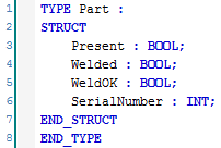
A good way to implement part tracking in TwinCAT 3 is to use a Structure. Imagine a welding machine where the operator places a part into the machine, it welds the part, and then the part is automatically ejected either into the good part bin, or into a reject chute. A reasonable Part structure might look like this:
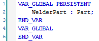
Part tracking data needs to survive the reboot of the controller PC, so we need to declare this as a persistent variable. Here I’ve created a new variable called WelderPart in a persistent section of a global variable list:
Tracking Part Presence
We presumably have a sensor or some other method to detect part presence. Perhaps an operator has to place a part in the fixture, we detect the part with a sensor, and then they have to push a button to initiate the cycle. When this happens we need to set the Present bit and generate a new serial #.
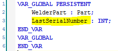
To generate a new serial #, we need a persistent LastSerialNumber variable:
Now create a new ladder logic Part Tracking program called TrackWelderPart:
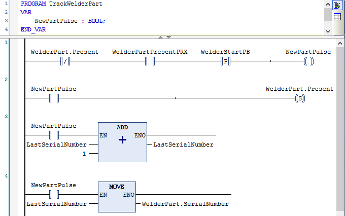
The first rung creates a “pulse” bit, sometimes called a “one-shot”. This is a bit that’s only on for one scan. The reason this is only on for one scan is because in the second rung, we use a Set coil to set the WelderPart.Present bit, of which we have a normally closed contact in the first rung.
The third and fourth rungs are responsible for incrementing the serial # and assigning it to the part tracking variable.
Notice so far that taking the part out and putting it back in (or a momentary failure of the part present sensor) won’t cause the part tracking to change. The part is still considered present, and the serial # is fixed.
Tracking Weld Status
The weld status is tracked presumably by feedback from the welder. Most welders operate by the PLC sending a weld trigger signal, and the welder responding with a WeldOK or a WeldFault signal. If that’s the case, we can track weld status like this:
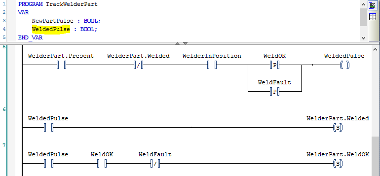
Again we’re creating a “pulse” bit that’s only on for one scan, called WeldedPulse. Notice also that the first three conditions on the first rung could be moved over to the program that fires the welder, and it could be used to create a coil called OkToWeld. You could then use OkToWeld here in place of those three contacts. This logic will prevent the welder from welding the same part twice, which is very important.
It’s also important to realize that this logic works equally well in both automatic or manual mode. As long as the welder fires correctly with a part present then we’ll track the weld status. This is useful both for testing and to prevent mis-tracking the part.
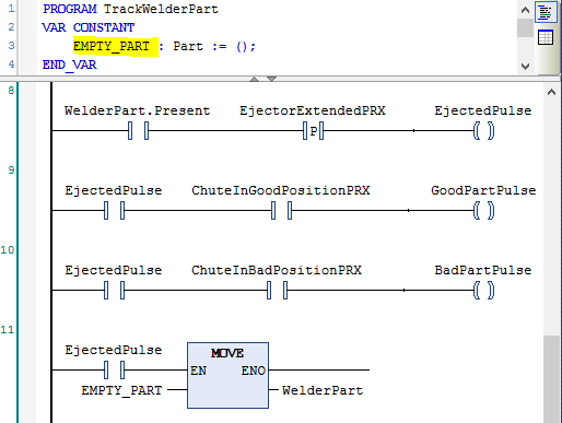
Tracking Part Removal
There are three ways this part can leave the welder:
- It can be ejected into the good part bin
- It can be ejected into the bad part chute
- An operator can remove it
I like to create a separate pulse for each event so that I can use that pulse bit for other tasks like part counters and logging events.
Let’s assume we have a Part Ejector cylinder and cylinder that toggles the chute between the good bin and rejected part chute position. Ejecting the part with the toggle in the good position sends it to the good part chute, and ejecting the part with the toggle in the bad position sends it to the bad part chute.
When removing the part from the part tracking memory, it needs to clear the entire structure. Thankfully there’s an easy way to do this. Declare a constant of type Part and use a MOVE instruction to copy the empty structure over to of the part tracking variable:
Somewhere else in your logic, you need to make sure that the ejector only extends if the chute position matches the part status, so the part tracking should have the Welded and WeldOK bits set in order to eject in the good position. Don’t let it eject a bad part into the good part bin even in manual mode.
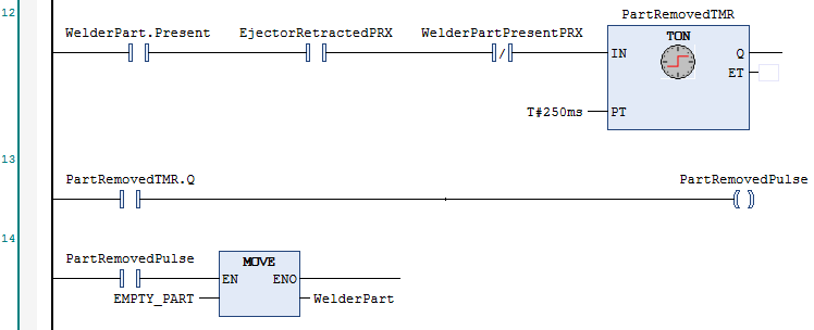
Recovering From Abnormal Conditions
Let’s assume the operator removed the part by hand. You have some options. One way to handle it is to just accept that the part was removed. I like to use a timer just to “debounce” the sensor a little bit:
However, unless manual removal is part of the normal process, I don’t like to automatically accept a part removal. I prefer creating a cycle stop fault, and then having the operator press a button to manually remove the part tracking data:
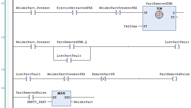
This is a nice handshake with the operator. The machine is saying, “I know you removed the part, and now I know that you know that I know that you removed a part.” In any relationship, communication is key.
If you happen to have a situation where the part can literally fall out, like a vacuum gripper on a robot, you typically monitor the vacuum feedback to make sure the part is still attached. In that case, if the vacuum feedback turns off while you’re supposed to have a part, that’s a pretty serious fault (typically an immediate-stop fault) because it detects a dropped fault. In that case, you need to get the operator to confirm the removal of the part because they need to remove the part from the machine (wherever it dropped). It’s also possible there’s something wrong with the gripper.
Tracking a Part From Station to Station
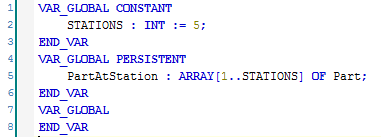
Machines often have automated transfer equipment such as conveyors, pick & place equipment or material handling robots to move parts around from station to station within the work cell. Imagine the case where a conveyor is moving the part from station 1 to station 2. Assume there’s a sensor at station 1 and station 2. We could use a persistent array to track the part at each station:
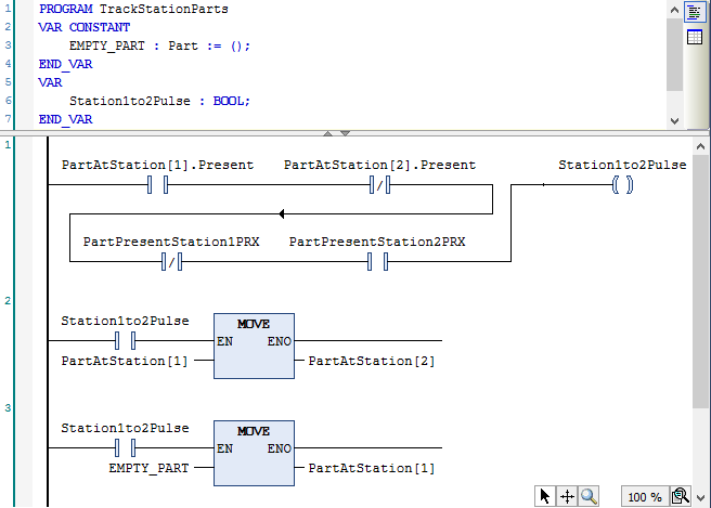
The logic to move a part from station 1 to station 2 might look like this:
Part Tracking in Rotary Tables
Rotary tables present an interesting challenge. A rotary table is a table that can continuously rotate in either direction. It has some number of part nests, and it moves parts around a cell by indexing the entire table forward one index distance so all the parts are moved from the current station to the next station in one move.
If you use an indexing table (where you extend a cylinder or run a motor until a sensor turns on) then you can usually get away with using logic like the conveyor-type logic above, except that you index all the stations simultaneously. This is no problem, just remember to index the last station first and the first station last, so you don’t overwrite the next station.
However, rotary tables can be more complicated than this. What happens if the operator is in manual mode and indexes a 4 position rotary table 4 times? Shouldn’t the original parts be back in their original locations? Does that mean you index the last station into the first station too? Also, what about servo-type rotary tables that run in reverse or index to half-station positions?
The problem is that we’ve modeled the situation wrong. The parts are always fixed in a certain nest, and the table position determines which station they’re at. It’s more correct to create a PartInNest tracking array:
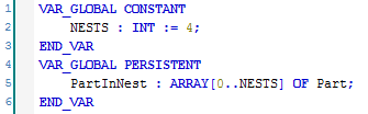
(I deliberately added an index 0 at the beginning to make the part tracking logic simpler later, as you’ll see. Nest 0 is an invalid nest, meaning no nest at station.)
Then you need to use the table position to determine which nest number is at each station (or 0 if no nest). In some cases this is done with an array of binary proxes (one prox indicates you’re in some position, and a set of other proxes indicate which one you’re in, so you’d need 2 to indicate 4 stations, 3 to indicate up to 8 stations, etc.). In other cases you have a servo with an angle position, and you use the angle position to figure out which nest is at each station. For now just imagine a function that returns an integer (nest number) for a given station:
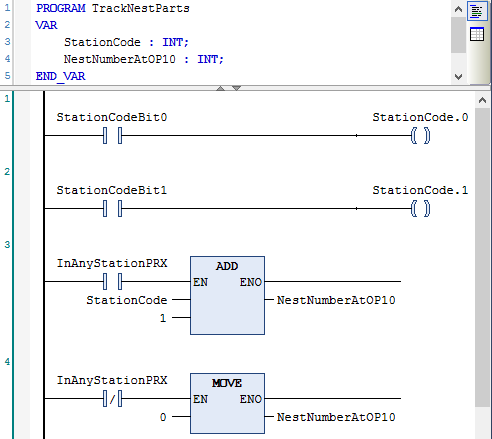
This is simplified logic. It assumes that if the proxes show off,off then nest 1 is at the OP10 station, and if it shows off,on then nest 2 is at the OP10 station, etc. You would have to customize it for your machine and for each station. This is just an example. Note that if no nest is in position it sets the nest number to 0.
Now there’s more than one way to do this. You could use NestInStation[NestNumberAtOP10].Present everywhere in your OP10 part tracking logic but the variable name starts to get really long, and it’s a bit complicated for an electrician to understand “indirect addressing”. Here’s another alternative… create a program that takes a Part as a VAR_IN_OUT, and call it like this:
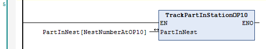
We’re doing something a little tricky here. We’re passing the actual nest part data by reference, meaning the OP10 part tracking program can read and write into that variable. Inside the program it looks like this:
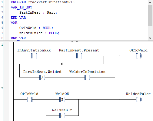
The logic is straightforward, the variable name lengths are reasonable, and you don’t have to worry about which nest is at the OP10 station because that’s handled by the outer program. Note that you have to use the InAnyStationPRX input to determine if you’re actually in a station, or else you’re looking at index 0.
By tracking the part in the nest, you don’t have to shift data around with MOVE instructions when you index the table, and you have the option of displaying the part data on the HMI both by station and by nest. You can even display the part tracking by nest when the table isn’t in an actual station position.
Conclusion
This has been a brief introductory tutorial to generalized part tracking in TwinCAT 3. In my experience you can build an arbitrarily large part tracking system based on these few simple concepts.
This chapter is part of the TwinCAT 3 Tutorial.